
Method and apparatus for increasing floating platform buoyancy

a floating platform and buoyancy technology, applied in the field of floating platform systems, can solve the problems of large capital expenditure, high cost of oil and gas recovery, and uneconomical production,

Inactive Publication Date: 2003-11-06
SEAHORSE EQUIP
View PDF7 Cites 12 Cited by
  • Summary
  • Abstract
  • Description
  • Claims
  • Application Information

AI Technical Summary

Benefits of technology

[0006] It is another object of the present invention to provide a floating platform whereby the payload capacity of the platform may be increased after the platform is located in the filed. Such an increase in payload capacity is provided by attaching a buoyancy module to the platform hull rather than redesigning the hull and node structure of the platform.
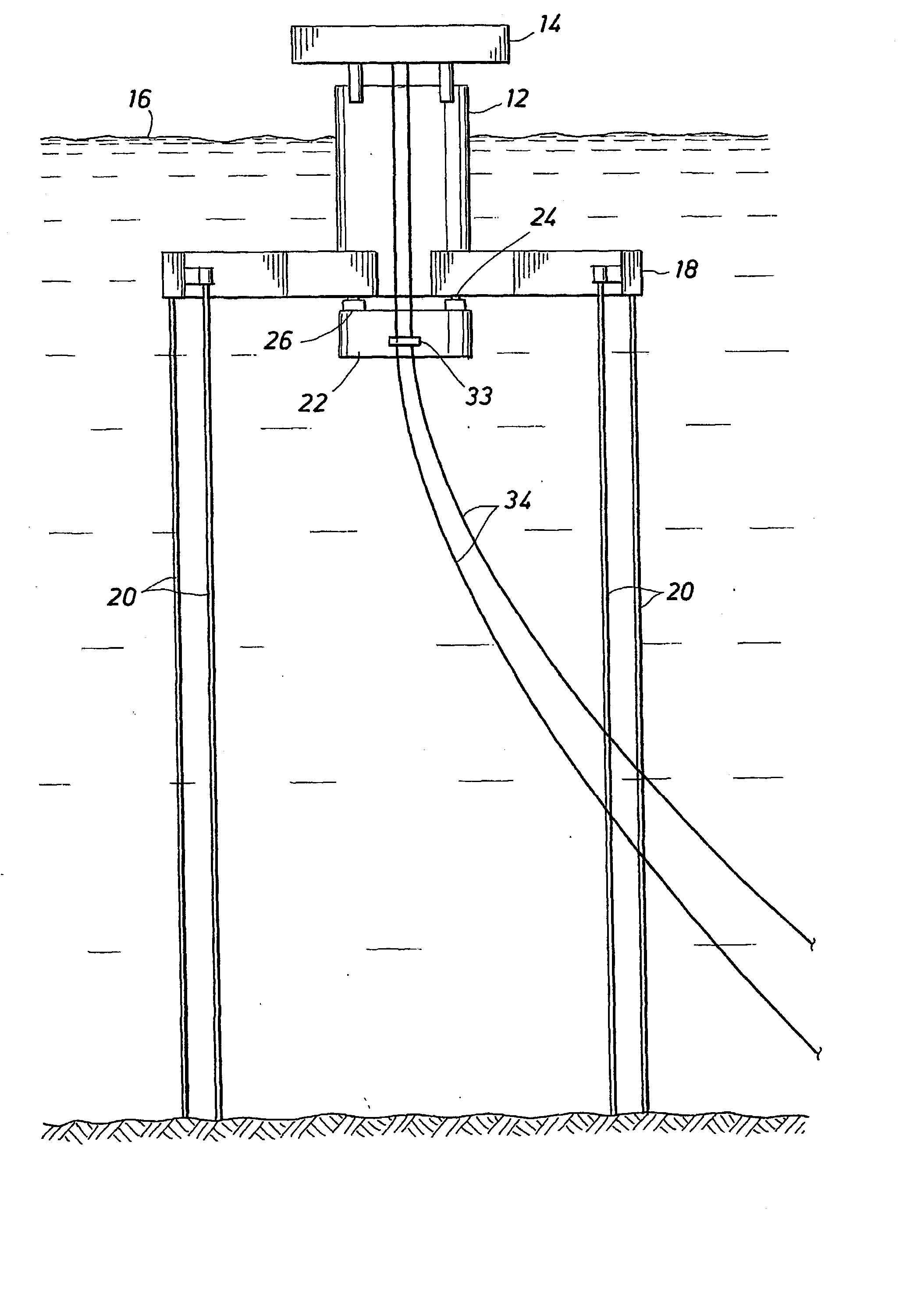
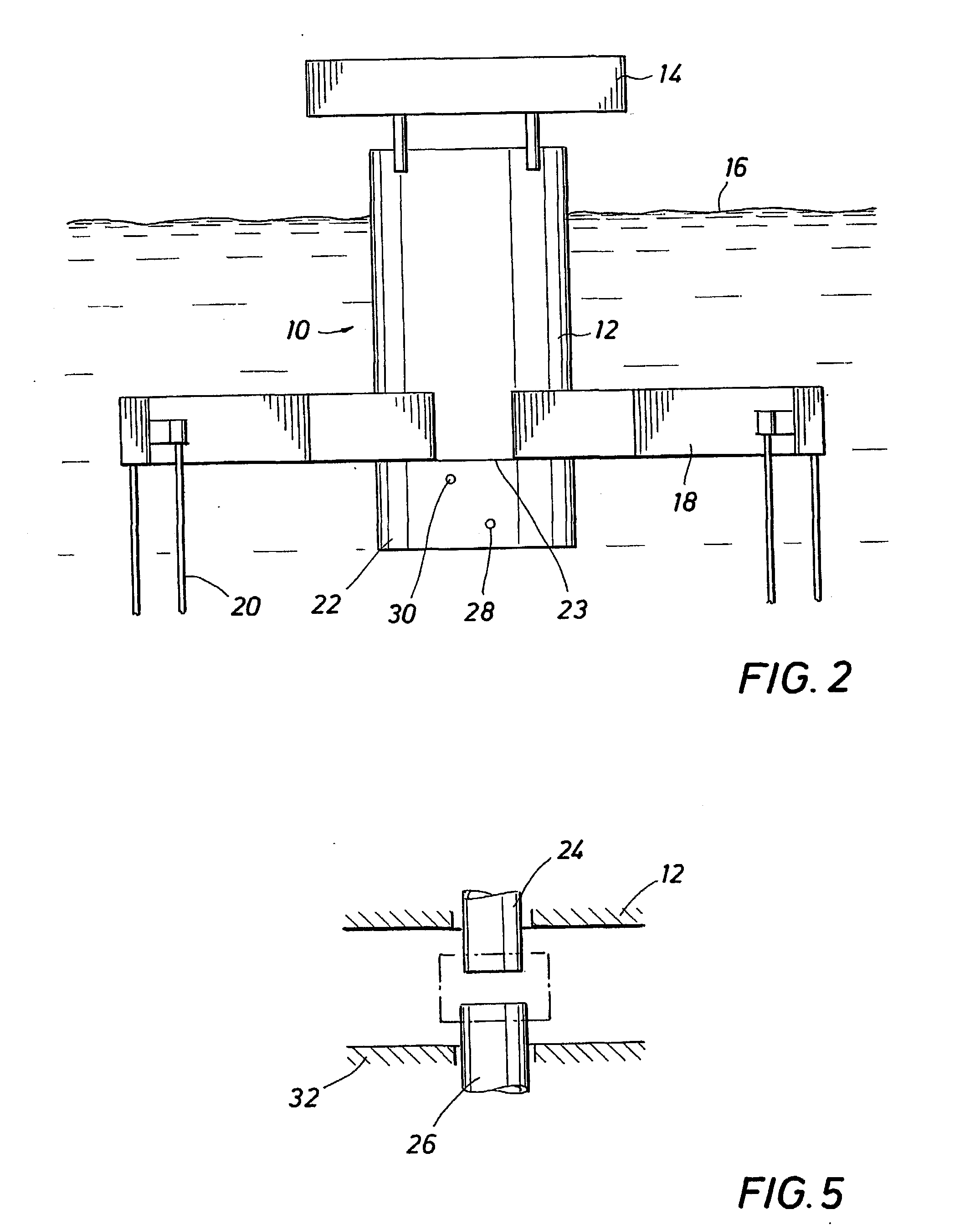
[0007] The present invention provides a floating platform for recovery of oil and gas from offshore oil and gas fields. The platform supports one or more decks above the water surface to accommodate equipment for drilling and processing oil, gas and water recovered from the oil and gas field. In a preferred embodiment, the platform includes a hull having a portion located substantially below the water surface, and including a portion which extends above the water surface. The platform hull includes a base and is anchored to the seabed by one or more tendons secured to the base of the hull at one end thereof and to the seabed at the opposite ends of the tendons. The payload carrying capacity of the platform is increased without redesigning the structural design of the platform hull by attaching a column extension to the bottom of the hull of the platform.

Problems solved by technology

The exploration for oil and gas deposits in offshore waters, and recovery of the oil and gas therefrom is very expensive.
Large capital expenditures are required and thus only large oil and gas deposits justify such expenditures.
Smaller oil and gas deposits usually do not justify large capital investments and therefore are deemed to be uneconomical to produce.
Even these systems, however, can be quite expensive to manufacture and install.
Other factors, such as the discovery of recoverable oil and gas from adjacent deposits may alter the payload requirements for a platform already in use.

Method used


Image

  • Method and apparatus for increasing floating platform buoyancy
  • Method and apparatus for increasing floating platform buoyancy
  • Method and apparatus for increasing floating platform buoyancy

Examples


Embodiment Construction

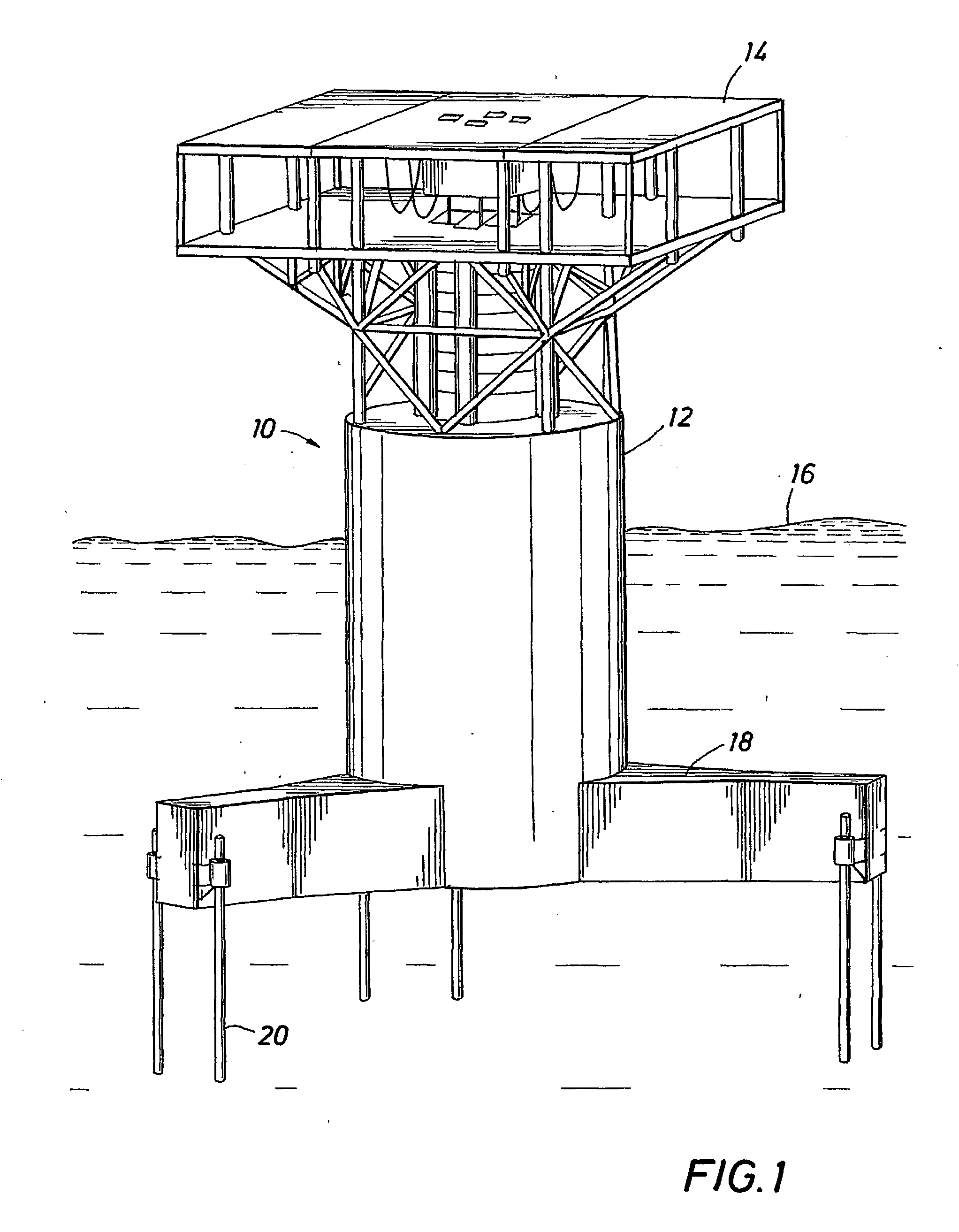
[0016] Referring first to FIG. 1, the floating platform of the invention is generally identified by the reference numeral 10. The platform 10 includes a central column or hull 12 which provides positive buoyancy and vertical support for the platform 10. One or more decks 14 are supported on the hull 12 above the water surface 16. Drilling and / or production equipment necessary for the recovery and processing of oil, gas and water recovered from the oil and gas field are secured on the deck 14.

[0017] The hull 12 extends upward from the base or keel of the hull 12. The base node of the hull 12 includes pontoons 18 extending radially outward from the hull 12. The platform 10 is anchored to the seabed by tendons 20 secured at one end thereof to the pontoons 18 and at the opposite ends thereof to foundation piles (not shown in the drawings) embedded in the seabed. The hull 12 provides sufficient buoyancy to support the payload of the platform 10, which payload includes the deck 14, drilli...


PUM


Abstract

A floating platform for recovery of oil and gas from offshore oil and gas fields includes a hull having a portion located substantially below the water surface, and including a portion thereof which extends above the water surface. The platform is anchored to the seabed by one or more tendons secured to the base of the hull and the seabed. The playload capacity of the floating platform is increased without redesigning the structural design of the hull by attaching a column extension or mounting a detachable buoyancy module to the lower end of the hull for accomodating changing platform pay load requirements.

Description

BACKGROUND OF THE DISCLOSURE[0001] The present invention relates generally to floating platform systems for testing and producing hydrocarbon formations found in deep (600-10,000 feet) offshore waters. More particularly, the invention relates to a method and system for changing the buoyancy of the floating platform to accommodate changes in platform payload and water depth requirements without redesigning the platform hull.[0002] The exploration for oil and gas deposits in offshore waters, and recovery of the oil and gas therefrom is very expensive. Large capital expenditures are required and thus only large oil and gas deposits justify such expenditures. Smaller oil and gas deposits usually do not justify large capital investments and therefore are deemed to be uneconomical to produce.[0003] Various methods and offshore production systems have been utilized to locate and recover offshore oil and gas deposits. Production systems such as converted Mobile Offshore Drilling Units ("MOD...

Claims


Application Information

Patent Timeline
IPC IPC(8): B63B1/04B63B3/08B63B9/04B63B9/06B63B21/50B63B35/44
CPCB63B35/4406B63B21/502
Inventor HORNE, EARL WILSONKYRIAKIDES, ANDREW
Owner SEAHORSE EQUIP
Learn More