UV-assisted grafting of pes and psf membranes

a technology of uv-assisted grafting and membranes, which is applied in the direction of membranes, filtration separation, separation processes, etc., can solve the problems of reducing productivity, reducing membrane permeability, and reducing flux

Inactive Publication Date: 2003-11-13
RENESSELAER POLYTECHNIC INST
View PDF5 Cites 8 Cited by
  • Summary
  • Abstract
  • Description
  • Claims
  • Application Information

AI Technical Summary

Problems solved by technology

A major obstacle in the incorporation of membrane processes into industrial operations is the problem of flux decline due to fouling during the ultrafiltration of biological products such as proteins.
Fouling not only decreases membrane permeability which reduces productivity due to longer filtration times, but also shortens membrane life due to the harsh chemicals necessary for cleaning.
Furthermore, fouling can alter membrane selectivity and lead to significant product loss through denaturation.
This causes narrowing or plugging of membrane pores, which results in decreased membrane permeability.
Irreversible fouling causes flux loss that is recovered only through the use of harsh detergents and/or chemicals.
Furthermore, after some time and under the right operating and solution conditions, further flux loss can occur because the adsorbed protein layer(s) can consolidate or compact into a more dense, higher flux-resistant layer.
These surface-modified membranes are not rewettable after they have been dried and, if dried, lose significant

Method used


Image

  • UV-assisted grafting of pes and psf membranes
  • UV-assisted grafting of pes and psf membranes
  • UV-assisted grafting of pes and psf membranes

Examples


example 2

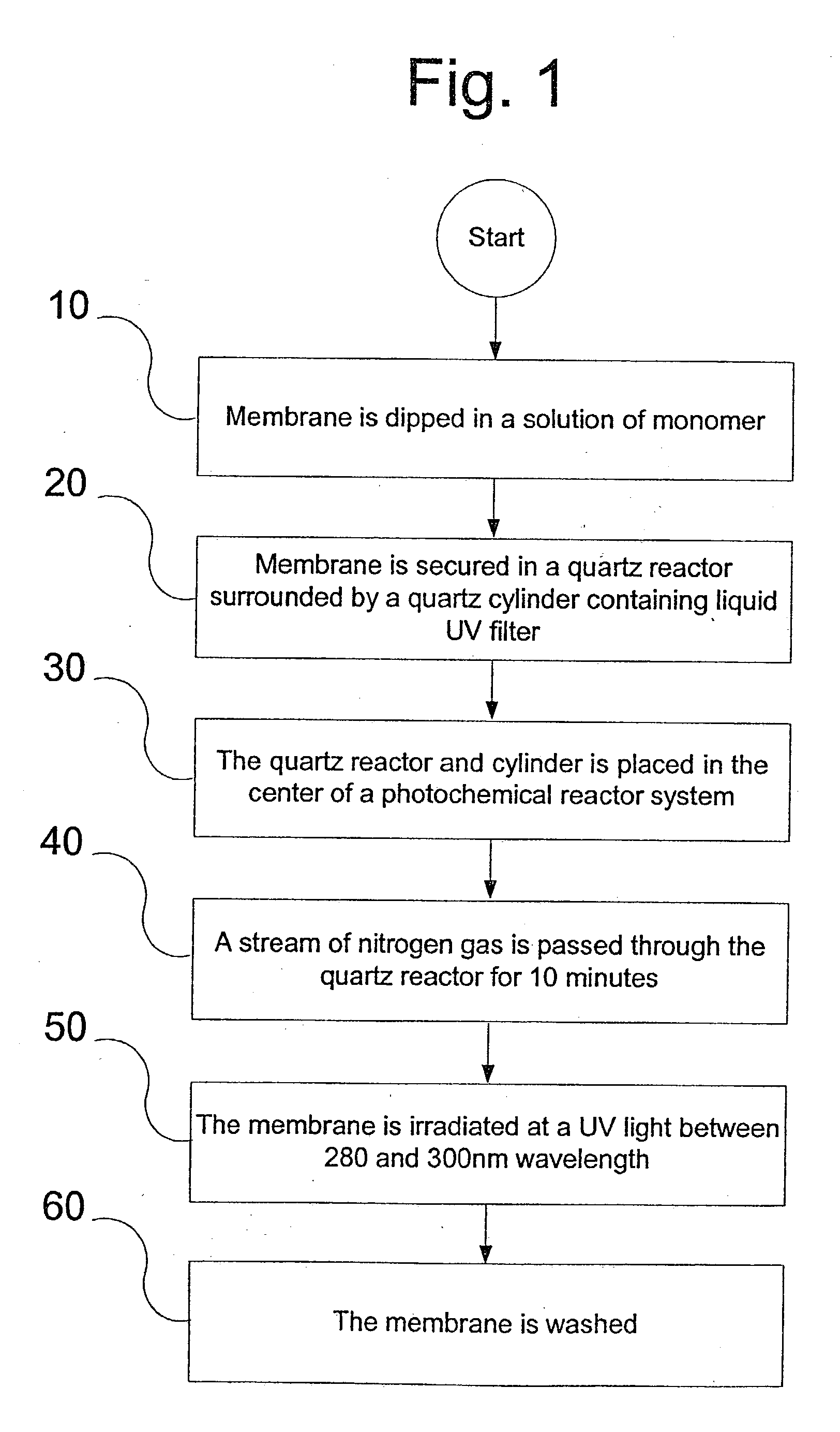
[0036] A 50 kDa Omega PES membrane from Pall corp, a 50 kDa Polysulfone ("PSF") GR51 PP membrane from Danish Separations Systems, and a 50 kDa regenerated cellulose membrane from Pall Filtron were provided. They were dipped in monomer solutions of 5% by weight NVP, AAG, and AAP. Only UV lamps that emit their maximum frequency at 300 nm were used to irradiate. The degree of grafting was compared. Degree of grafting ("DG") equals the ratio of the peak height of the amide I carbonyl stretch in the monomer molecule to that of the benzene ring carbon-carbon double bond stretch. For the PES membrane, optimal grafting conditions with the three different monomers was at the lowest irradiation energy. PES is much more sensitive than PSf toward UV radiation, and is preferred, but both are acceptable for use.

example 3

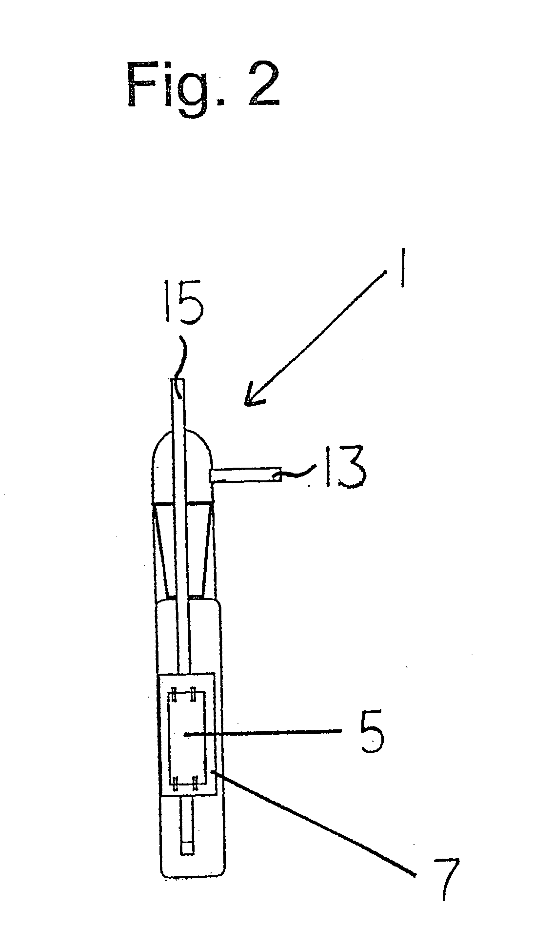
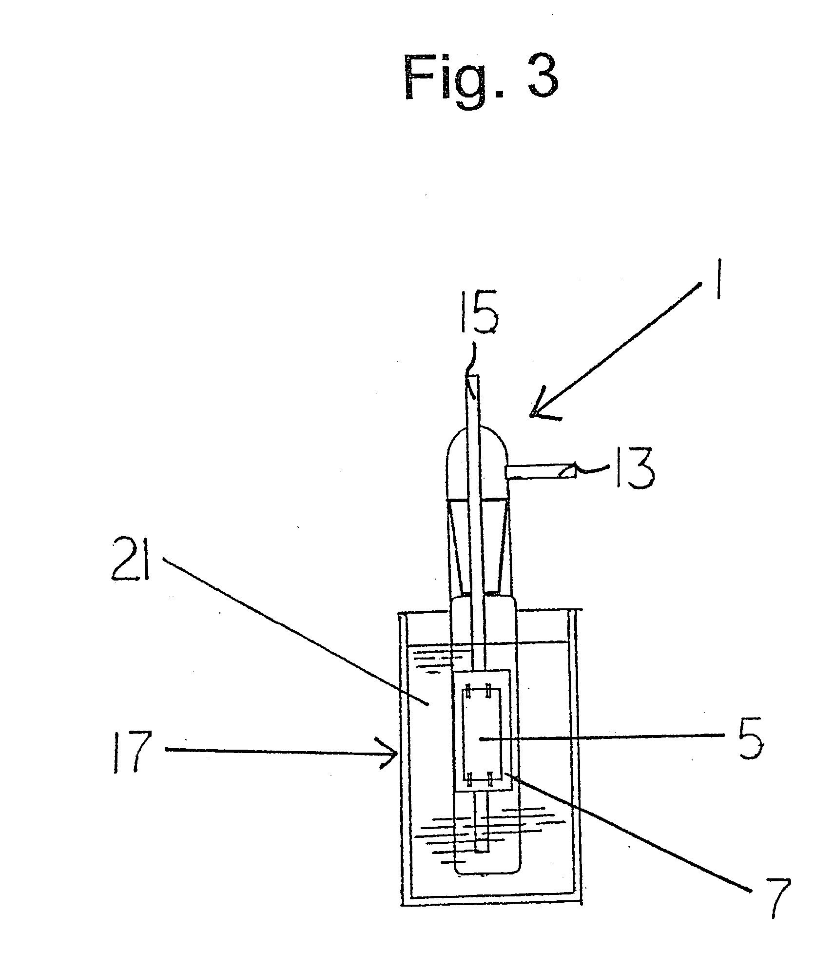
[0037] A 50 kDa PES membrane was provided. Dip modification was with 5 wt % NVP for different times (hence different irradiation energies) with the listed conditions. Two filters, benzene liquid and aromatic polyester film, were used with 300 nm UV light. A regenerated cellulose membrane was used as the control surface. A solution of 0.1 wt % BSA in 10 mM PBS at pH=7.4 and 22.degree. C. was filtered according to a constant volume diafiltration protocol.

[0038] FIG. 5 shows a graph plotting protein solution permeability as a function of irradiation energy exposure. The black bars represent the pure buffer permeability and the grey bars represent the protein solution permeability. Permeability was optimal with a benzene filter and irradiation at 300 nm wavelength. Permeability, along with solute flux and retention were optimal at lower irradiation energies.


PUM

PropertyMeasurementUnit
Wavelengthaaaaaaaaaa

Abstract

An ultrafiltration membrane is modified to exhibit low protein fouling and yet maintains a greater fraction of the original membrane permeability and retention properties after modification. This is achieved by grafting monomer onto the surface of a highly photoactive membrane such as polyethersulfone, via the process of dipping the polymeric membrane into a solution containing one or more monomers and a chain transfer agent, removing the membrane from the solution, securing the membrane inside of a quartz vessel contained within another vessel of liquid filter, and irradiating the membrane with a UV light at a wavelength between the range of 280 nm and 300 nm. High density grafting and shorter grafted monomer chain length result in low protein fouling and retention of permeability.

Description

[0001] This application claims the benefit of provisional application numbers:1 60 / 238,209 Filing Date: Oct. 5, 2000 60 / 268,098 Filing Date: Feb. 12, 2001 60 / 270,233 Filing Date: Feb. 21, 2001FIELD AND BACKGROUND OF THE INVENTION[0002] The present invention relates in general to ultrafiltration membranes, and in particular to a new and useful polyethersulfone membrane and method for making such membrane by graft polymerization of particular vinyl monomers in the presence of UV radiation and a filter so that the membrane exhibits high solute retention, high permeability, and low fouling characteristics.[0003] Ultrafiltration membranes have found widespread use in the food and biotechnology industries. Ultrafiltration (UF) has been applied in the processing of normal and transgenic milk, cheese and eggs, whey and potato protein recovery, the clarification of juices and wine, the recovery of proteins from animal blood, and the purification of water. UF is also used in the biotechnology...

Claims


Application Information

Patent Timeline
IPC IPC(8): B01D67/00B01D69/02B01D71/68B01D71/78C08F261/00C08F273/00C08F291/06C08F291/14C08J7/18C08L51/08
CPCB01D67/0093B01D71/68C08F261/00C08F273/00B01D2323/385C08F291/14C08J7/18C08J2381/06C08L51/08C08F291/06B01D67/00931
Inventor BELFORT, GEORGESCRIVELLO, JAMES VPIERACCI, JOHN
Owner RENESSELAER POLYTECHNIC INST
Why Eureka
Try Eureka