Implantable antenna for use with an implantable medical device

a medical device and implantable technology, applied in the field of implantable medical devices, can solve the problems of inconvenient patient and staff conducting procedures, relative short distance, and low maximum data rate of inductive interfaces

Inactive Publication Date: 2003-11-20
ST JUDE MEDICAL
View PDF9 Cites 70 Cited by
  • Summary
  • Abstract
  • Description
  • Claims
  • Application Information

AI Technical Summary

Benefits of technology

[0014] In a preferred embodiment of the inventive antenna arrangement, the substrate overlaps a section of the patch plane along (at least one) sub-segment of the at least one second segment. An advantage thus attained is that the losses in the dissipative medium represented by the body tissue are further reduced.
[0018] In a preferred embodiment of the implantable medical device of the invention, the antenna arrangement is located in a recess of an outer side of a casing to the device. This is advantageous because a slim device design is thus made possible.
[0021] In another preferred embodiment of the implantable medical device of the invention, the patch plane is tilted with respect to the ground plane, such that the arrangement attains horn antenna properties. This, in turn, results in an antenna with an increased bandwidth, since it facilitates the propagation of the outgoing electromagnetic waves. Moreover, the efficiency of the antenna is enhanced due to an increased radiation resistance. Preferably, the patch plane is tilted such that the distance between the patch plane and the ground plane is shortest at a point where the grounding member connects to the patch plane.
[0023] A general advantage with the present invention is that simple antenna geometry is provided, which can be manufactured by means of a fairly uncomplicated production process. Furthermore, the inventive antenna geometry results in relatively low ohmic losses.

Problems solved by technology

However, the inductive interface requires a relatively short distance (on the order of centimeters) between the implanted device and the extracorporal unit with which it communicates.
This, in turn, may be inconvenient for the patient as well as impractical for the personnel conducting the procedure.
Moreover, the maximum data rate for an inductive interface is relatively low, which results in practical limitations as to the amount of data that can be communicated.
Although the above-mentioned solutions generally represent improvements in comparison to an inductive link regarding data rate and communication range, they fail to present a telemetry solution with satisfactory power efficiency and sufficiently small physical dimensions of the antenna.
However, low power consumption is at least as important.
The antenna's physical dimensions thus are limited, however its geometry becomes intricate.
Moreover, the design is inclined to cause large ohmic losses and consequently not be particularly power efficient.
Again, this results in a slim and uncomplicated design of the device.
Furthermore, the inventive antenna geometry results in relatively low ohmic losses.

Method used


Image

  • Implantable antenna for use with an implantable medical device
  • Implantable antenna for use with an implantable medical device
  • Implantable antenna for use with an implantable medical device

Examples


Embodiment Construction

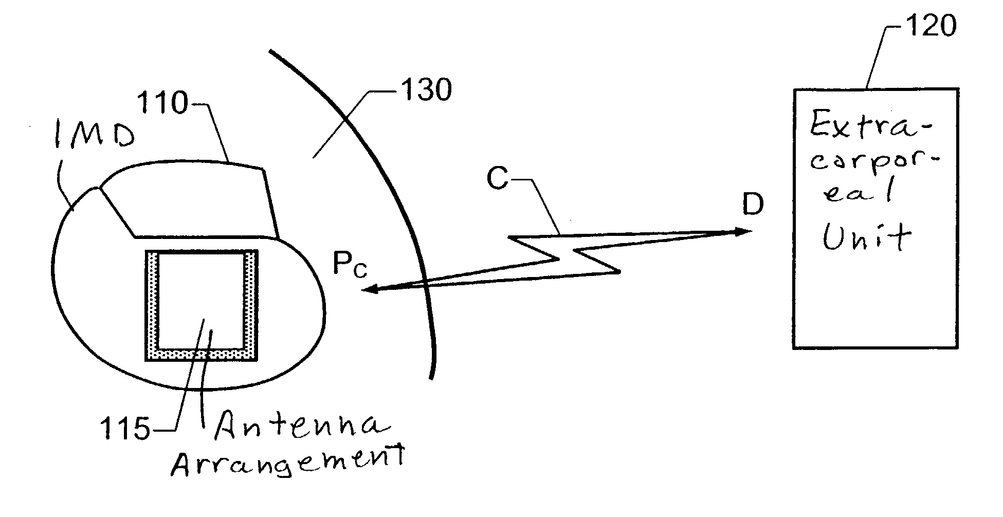
[0036] A wireless communication scenario involving an IMD 110 and an extracorporal unit 120 is shown schematically in FIG. 1. Data D and Pc may here be transferred in both directions between the IMD 110 and the extracorporal unit 120 over a radio link C. Typically, parameter settings or updating software Pc is sent from the unit 120 to the IMD 110 while measurement data D is sent in the opposite direction for various monitoring and diagnostic purposes.

[0037] According to the invention, an antenna arrangement 115 in the IMD 110 is used to exchange modulated electromagnetic energy with the surrounding transmission medium, i.e. the relevant body tissue 130. Specifically, this means that outgoing radio signals D are coupled through the body 130 and out into the contiguous environment, such as the air. The radio signals D then continue to propagate via the air to the extracorporal unit 120 where they are received, for example by a conventional radio antenna. Correspondingly, incoming rad...


PUM


Abstract

For wireless data exchange between an implantable medical device and an extracorporal unit by means of an antenna arrangement for communicating radio frequent signals, the antenna arrangement includes a patch plane having a perimeter, a ground plane of an electrically conducting material and a dielectric substrate filling a volume between the patch plane and the ground plane. The ground plane has an area which is larger than the patch plane and is located in relation to the patch plane such that a perpendicular projection of the patch plane onto the ground plane falls entirely within the ground plane. A grounding member connects the patch plane electrically to the ground plane at a first segment of the perimeter. The substrate has a comparatively high relative permittivity and extends a well-defined distance outside the volume between the patch plane and the ground plane with respect to at least one second segment of the perimeter. A non-conducting region thus is created outside the patch plane and therefore only a relatively small amount of electromagnetic losses will occur in this region.

Description

[0001] 1. Field of the Invention[0002] The present invention relates generally to an implantable medical device of the type associated with means for wireless data exchange with an extracorporal unit. More particularly the invention relates to an antenna arrangement for such data exchange.[0003] 2. Description of the Prior Art[0004] It is desirable for patient comfort for an implantable medical device (IMD) to remain in the body for as long a time as possible without explantation. Therefore, it is advantageous for the IMD to communicate with an external unit while the device is still implanted. Conventionally, status information and measurement parameters have been read out from implanted devices via an inductive telemetry interface. This type of interface is also usable for transferring of data in the opposite direction, for example when adjusting parameters pertaining to the operation of the IMD or when updating the device's program code to a newer version. However, the inductive ...

Claims


Application Information

Patent Timeline
Patent Type & Authority Applications(United States)
IPC IPC(8): A61N1/372H01Q9/04
CPCH01Q9/0421A61N1/37229
Inventor KARLSSON, ANDERSABRAHAMSON, HANSLINDBERG, MAGNUS
Owner ST JUDE MEDICAL
Why Eureka
Try Eureka