Process for producing olefinic polymer

a technology of olefinic polymer and polymer, which is applied in the direction of chemical/physical processes, chemistry apparatus and processes, etc., can solve the problems of difficult to evenly remove heat large problem concerning the removal of polymerization heat, and difficulty in removing heat evenly from the fluidized bed, etc., to achieve high heat removal efficiency and high melting efficiency

Inactive Publication Date: 2003-11-27
MITSUI CHEM INC
View PDF8 Cites 4 Cited by
  • Summary
  • Abstract
  • Description
  • Claims
  • Application Information

AI Technical Summary

Benefits of technology

0168] According to the present invention, the vapor phase polymerization of olefins using a fluidized-bed reactor can be carried out with high heat removal efficiency and polymer sheeting or melting is scarcely caused by heat localization when producing an olefinic polymer.
0169] The present invention will be hereinafter explained in more detail by way of examples, which, however, are not intended to be limiting of the present invention.

Problems solved by technology
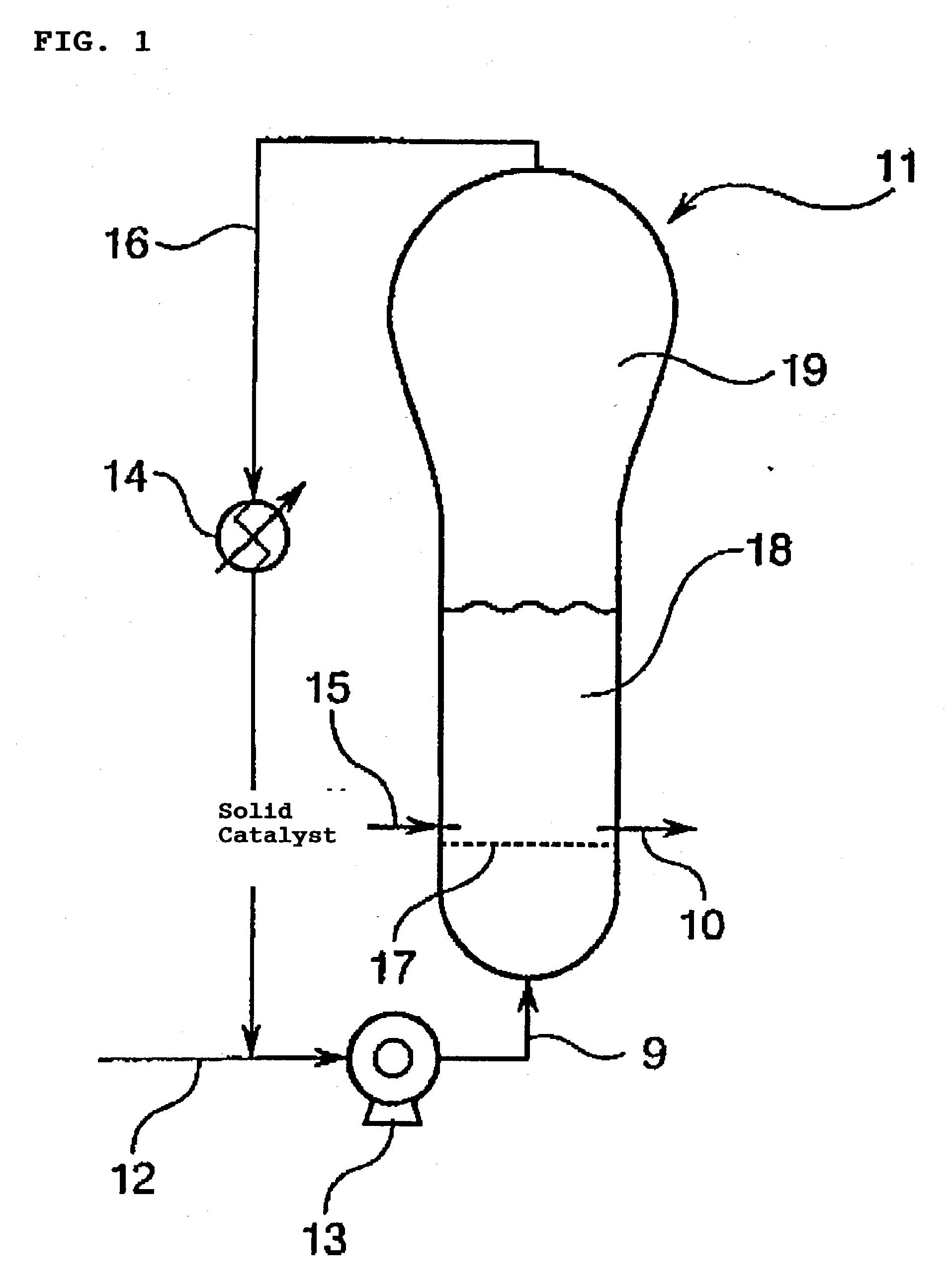
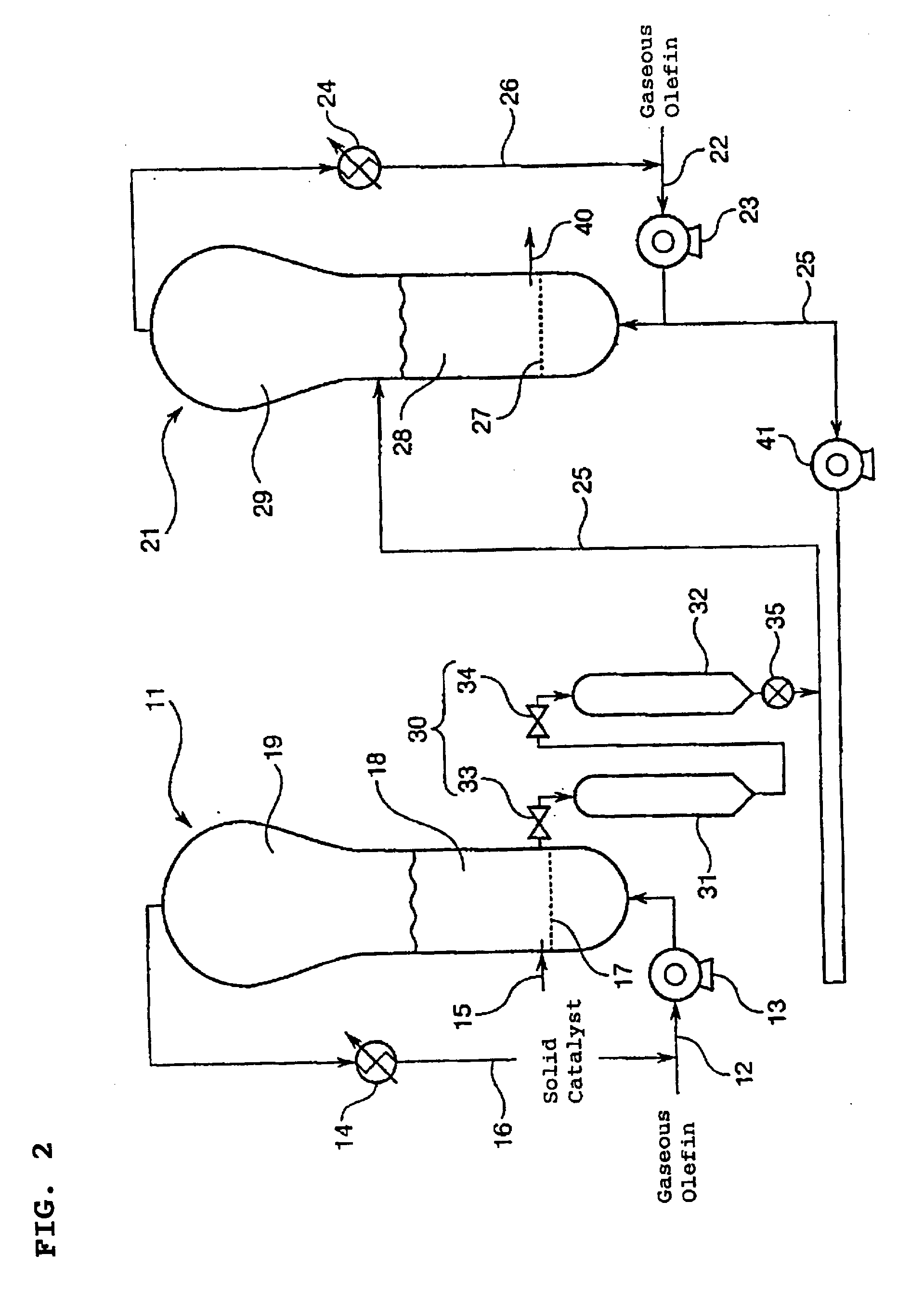
In such a vapor phase polymerization method, there is a large problem concerning the removal of polymerization heat.
However, even if the conventional heat removing method as aforementioned is adopted, it is difficult to remove heat evenly from the fluidized-bed and therefore local heating in the fluidized-bed is easily caused, giving rise to the sheeting and melting polymer problem.
When such a sheet or melting polymer is produced, the polymer is deposited on the gas distributing plate disposed on the lower portion of the fluidized-bed and the deposited polymer becomes an obstacle to keep a normal fluidized state and also clogs the holes of the gas distributing plate, which occasionally hinders the normal operation of the reaction system significantly.

Method used


Image

  • Process for producing olefinic polymer
  • Process for producing olefinic polymer
  • Process for producing olefinic polymer

Examples


example 1

[0170] (Preparation of a Solid Catalyst Component)

[0171] 10 kg of silica (SiO.sub.2) which had been dried at 250.degree. c. for 10 hours was suspended in 154 l of toluene, which was then cooled to 0.degree. c. To the suspension solution was added dropwise 50.5 l of a toluene solution of methylaluminoxane (Al=1.52 mol / l) over one hour with keeping the temperature of the suspension solution at 0 to 5.degree. c. In succession, the resulting solution was kept at 0.degree. c. for 30 minutes, then raised to 95.degree. c. over 1.5 hours and kept at 95.degree. c. for 4 hours.

[0172] Thereafter, the solution was dropped to 60.degree. c. and the supernatant was removed by decantation. The solid catalyst component obtained in this manner was washed twice with toluene and then redispersed in 100 l of toluene to be a total amount of 160 l.

[0173] 22.0 l of a toluene solution of bis(1,3-n-butylmethylcyclopentadien-yl)zirconium dichloride (Zr=25.7 mmol / l) was added dropwise to the obtained suspensio...


PUM

PropertyMeasurementUnit
pressureaaaaaaaaaa
pressureaaaaaaaaaa
apex angle θ2aaaaaaaaaa

Abstract

The process for producing an olefinic polymer comprises introducing a saturated aliphatic hydrocarbon in a liquid phase state and in a vapor phase state into the aforementioned fluidized-bed and (co)polymerizing in the condition that when the inside radius of the cylinder section of the fluidized-bed reactor is defined as a distance of 1, the relationship between the concentration (C1) of the saturated aliphatic hydrocarbon put in a liquid state in the peripheral portion of the cylinder section at a relative distance of 0.7 to 1.0 from the center of the cylinder section as a start point and the concentration (C2) of the saturated aliphatic hydrocarbon put in a liquid state in the center portion of the cylinder section at a relative distance less than 0.7 from the center fulfills the following equation: C1>C2 at a place close to the upstream section of said gas distributing plate.

Description

[0001] The present invention relates to a process for producing an olefinic polymer, and, particularly to a process for producing an olefinic polymer wherein local heating is scarcely caused in a fluidized-bed.[0002] Polyolefins are used in various uses. For example, films formed of a straight-chain low-density polyethylene (LLDPE) are superior in various characteristics, for example, these films have excellent heat sealing characteristics, high softness and high toughness, and it also have good water resistance, humidity resistance and chemical resistance and are inexpensive, and are therefore widely utilized.[0003] These polyolefins are typically produced by a liquid phase polymerization method such as solution polymerization and slurry polymerization. Particularly LLDPEs are produced by copolymerizing ethylene with an .alpha.-olefin having 4 or more carbon atoms in the presence of a Ziegler catalyst by using a liquid phase polymerization method.[0004] In the meantime, if such a p...

Claims


Application Information

Patent Timeline
Patent Type & Authority Applications(United States)
IPC IPC(8): B01J8/24C08F2/34C08F210/16
CPCB01J8/1827C08F210/16C08F2/001C08F2/34C08F2/005C08F210/14C08F2500/12C08F2500/18C08F2500/17
Inventor OHTANI, SATORUABE, SHINJINISHIDA, HIROTO
Owner MITSUI CHEM INC
Why Eureka
Try Eureka