Perfluoride processing apparatus
a technology of processing apparatus and perfluoride, which is applied in the direction of mechanical apparatus, machine/engine, separation process, etc., can solve the problem of taking a long time to install these facilities
- Summary
- Abstract
- Description
- Claims
- Application Information
AI Technical Summary
Benefits of technology
Problems solved by technology
Method used
Image
Examples
embodiment 1
[0022] Embodiment 1
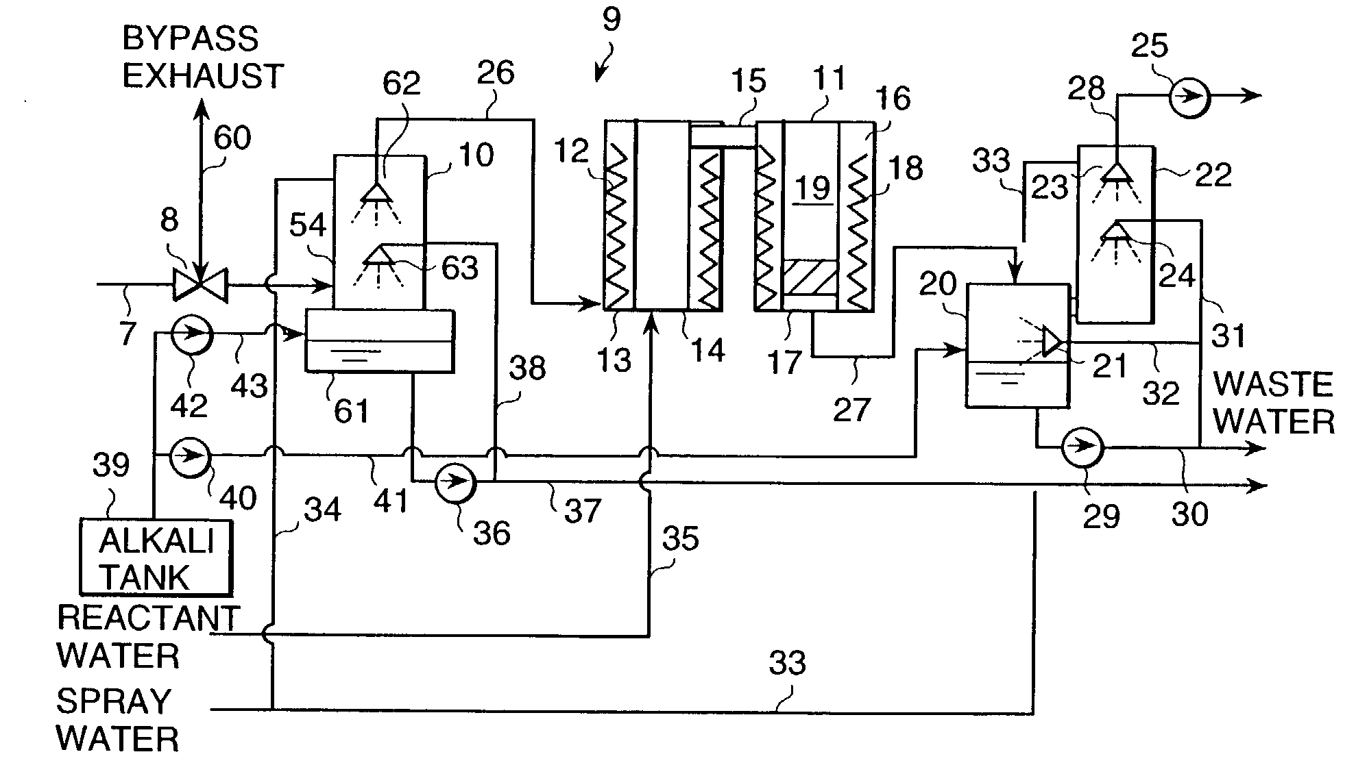
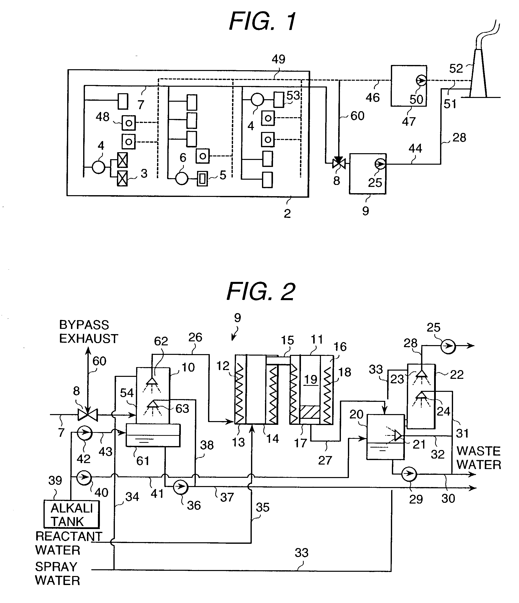
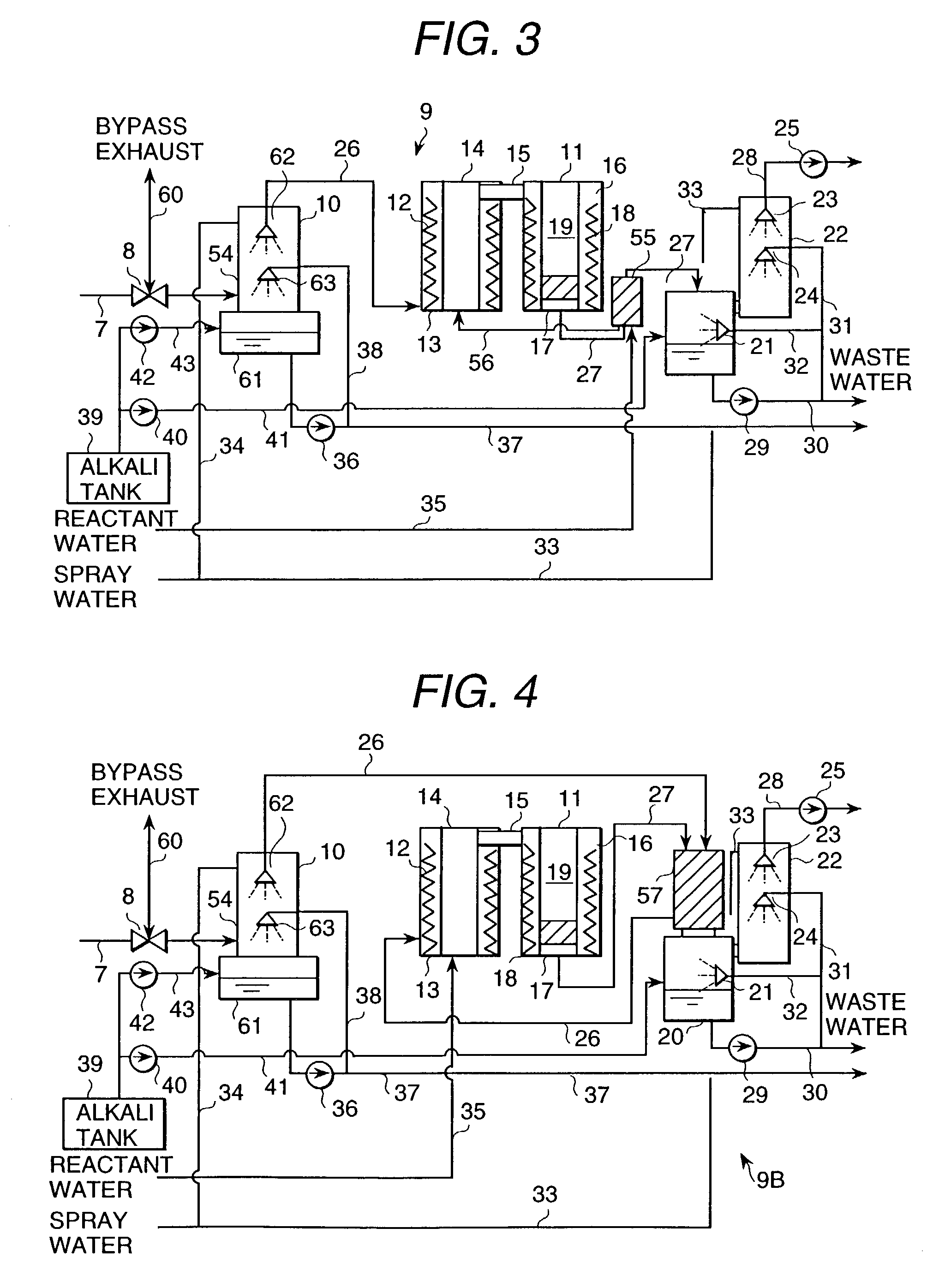
[0023] Prior to explanation of a perfluoride processing apparatus, that is, PFC processing apparatus, in accordance with one preferred embodiment of the present invention, a schematic configuration of a semiconductor fabrication system including a semiconductor fabrication factory will first be explained with reference to FIG. 1 below. The illustrative semiconductor fabrication system is equipped with a semiconductor fabrication factory 1, a PFC decomposition device 44, and a factory acidic gas processing equipment 46. The building of semiconductor fabrication factory 1 has therein a clean room 2. A plurality of semiconductor fabrication apparatuses including etchers such as poly-etchers 3, an oxide film etcher 5, and a metal etcher 53 are installed within the clean room 2. Also installed within the clean room 2 is a plurality of gas supply devices 48. The individual gas supply device 48 is the one that supplies gases (such as PFC gas or the like) required at etch...
embodiment 2
[0059] Embodiment 2
[0060] A PFC processing apparatus in accordance with another embodiment of the present invention will be explained with reference to FIG. 5. The PFC processing apparatus 44A of this embodiment is arranged so that the exhaust duct 28 is connected to the acidic gas removing device 47 in the PFC processing apparatus 44 shown in FIG. 1. An arrangement of the other part of PFC processing apparatus 44A is the same as that of the PFC processing apparatus 44. In this embodiment, an exhaust gas which was drained out of the acidic gas removing device 22 of the PFC decomposition device 9 is supplied through the exhaust gas duct 28 to the acidic gas removing device 47. Due to this, in case the acidic gas removing device 22 decreases in acidic gas removal functionality, any acidic gas to be produced by PFC decomposition within the reaction unit 16 can be removed by the acidic gas removing device 47. In this way, it is possible to use the acidic gas removing device 47 as a back...
embodiment 3
[0062] Embodiment 3
[0063] A PFC processing apparatus in accordance with still another embodiment of the present invention will be explained below. The PFC processing apparatus 44B of this embodiment is arranged so that the PFC decomposition device 9 in the PFC processing apparatus 44 shown in FIG. 1 is replaced by a PFC decomposition device 9C shown in FIG. 6. The other arrangement of the PFC processing apparatus 44B is the same as that of the PFC processing apparatus 44. An arrangement of the PFC decomposition device 9C that is used in the PFC processing apparatus 44B will be explained. Whereas the PFC decomposition device 9 is a wet-type PFC decomposition device in which waste water generates the PFC decomposition device 9C used in this embodiment is a dry-type PFC decomposition device in which no waste water generates.
[0064] The PFC decomposition device 9C is equipped with a reaction unit 11, filer devices 65, 66 and fine-particle / powder silo 81. The duct 7 is coupled to a lower-...
PUM
| Property | Measurement | Unit |
|---|---|---|
| Angle | aaaaa | aaaaa |
| Temperature | aaaaa | aaaaa |
| Time | aaaaa | aaaaa |
Abstract
Description
Claims
Application Information
 - R&D
- Intellectual Property
- Life Sciences
- Materials
- Tech Scout
- Unparalleled Data Quality
- Higher Quality Content
- 60% Fewer Hallucinations
Browse by: Latest US Patents, China's latest patents, Technical Efficacy Thesaurus, Application Domain, Technology Topic, Popular Technical Reports.
© 2025 PatSnap. All rights reserved.Legal|Privacy policy|Modern Slavery Act Transparency Statement|Sitemap|About US| Contact US: help@patsnap.com


