
Hydrocarbon adsorbent state determining apparatus

Inactive Publication Date: 2004-01-08
HONDA MOTOR CO LTD
View PDF4 Cites 8 Cited by
  • Summary
  • Abstract
  • Description
  • Claims
  • Application Information

AI Technical Summary

Benefits of technology

[0007] The present invention has been made to solve the problem mentioned above, and it is an object of the invention to provide a hydrocarbon adsorbent state determining apparatus which is capable of compensating the ability of a hydrocarbon adsorbent to adsorb moisture for fluctuations due to a change in the flow velocity of exhaust gases to accurately determine the state of the hydrocarbon adsorbent, including a deterioration thereof, irrespective of the change in the flow velocity of exhaust gases.
[0011] Moisture within exhaust gases is initially adsorbed by the hydrocarbon adsorbent after the internal combustion engine is started. Subsequently, at the time the hydrocarbon adsorbent is saturated in accordance with its ability to adsorb moisture, a portion of moisture which can no longer be adsorbed by the hydrocarbon adsorbent passes therethrough. Therefore, the humidity of exhaust gases which pave passed through the hydrocarbon adsorbent is maintained low until the saturation of the hydrocarbon adsorbent, and changes toward a high humidity region immediately after the saturation. As such, a changing state including the change timing reflects the ability of the hydrocarbon adsorbent to adsorb moisture. Thus, according to this preferred embodiment of the hydrocarbon adsorbent state determining apparatus, the state of the hydrocarbon adsorbent can be more accurately determined in accordance with a change in the detected value of the humidity detecting means from the start of the internal combustion engine.
[0015] According to this preferred embodiment of the hydrocarbon adsorbent state determining apparatus, the humidity of exhaust gases flowing into the hydrocarbon adsorbent (upstream humidity) is detected at a location upstream of the hydrocarbon adsorbent, in addition to the humidity of exhaust gases which have passed through the hydrocarbon adsorbent, and the state of the hydrocarbon adsorbent is determined in accordance further with the detected upstream humidity. Consequently, the detected upstream humidity can be based to precisely estimate a timing at which exhaust gases actually reach the hydrocarbon adsorber after the internal combustion engine is started, thereby more accurately determining the state of the hydrocarbon adsorbent.

Problems solved by technology

As a result, the adsorbent is deteriorated, causing a gradual degradation in the ability of the adsorbent to adsorb the hydrocarbons.
Presumably, this is because exhaust gases come in contact with the adsorbent with a lower probability for a shorter time as the exhaust gases flow at a higher velocity (more likely to pass through the adsorbent), resulting in a lower apparent ability of the adsorbent to adsorb moisture.
For this reason, when exhaust gases flow at a high velocity, the state determining apparatus can erroneously determine, from the under-evaluated ability of the adsorbent to adsorb moisture, that the adsorbent is deteriorated though it is in fact normal.
On the other hand, when exhaust gases flow at a low velocity, the state determining apparatus can erroneously determine, from the over-evaluated ability of the adsorbent to adsorb moisture, that the adsorbent is normal though it is in fact deteriorated.
Thus, the state determining apparatus can fail to ensure a sufficient accuracy for determining a deterioration of the adsorbent, and therefore still leaves room for improvement in this respect.

Method used


Image

  • Hydrocarbon adsorbent state determining apparatus
  • Hydrocarbon adsorbent state determining apparatus
  • Hydrocarbon adsorbent state determining apparatus

Examples


Embodiment Construction

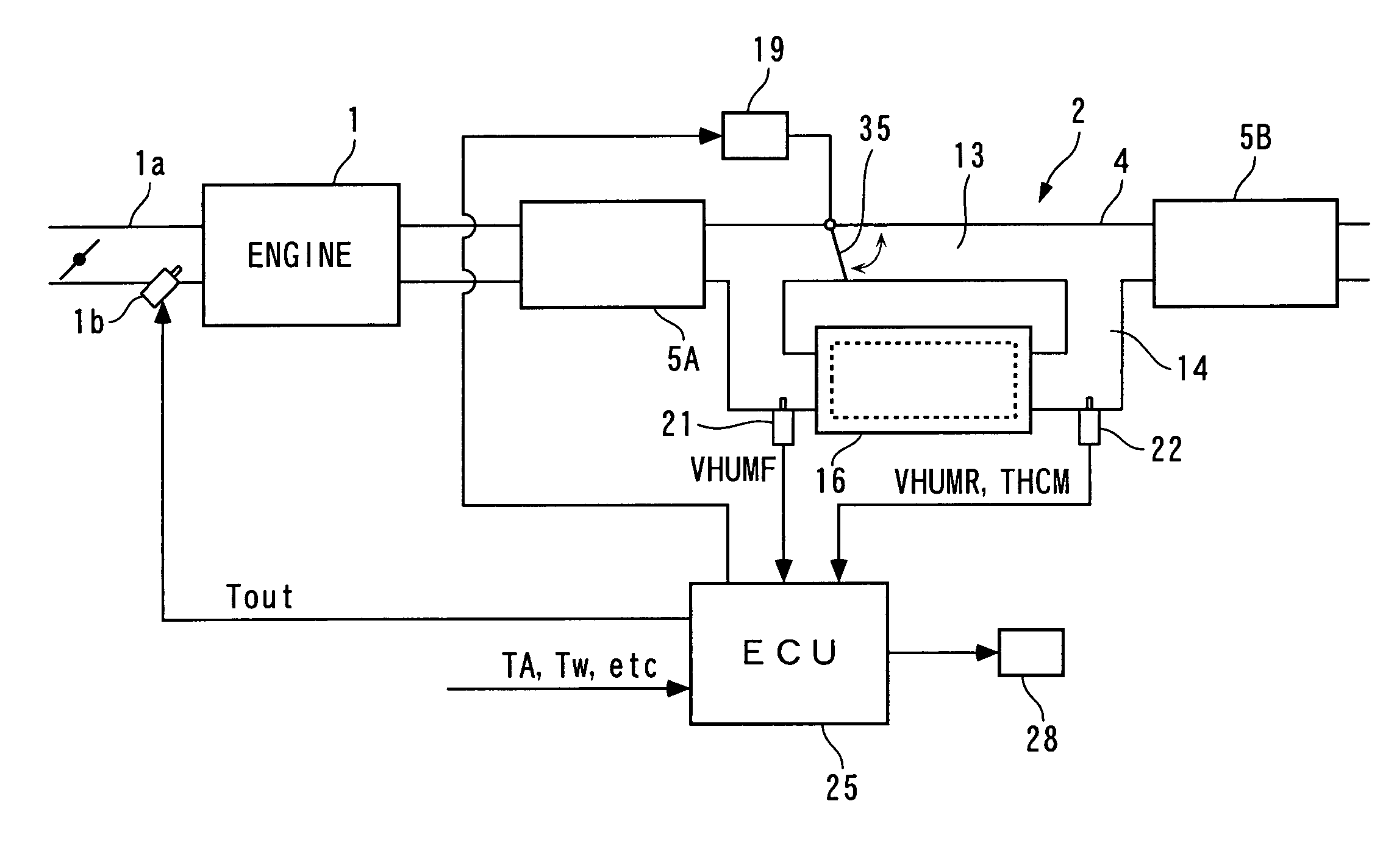
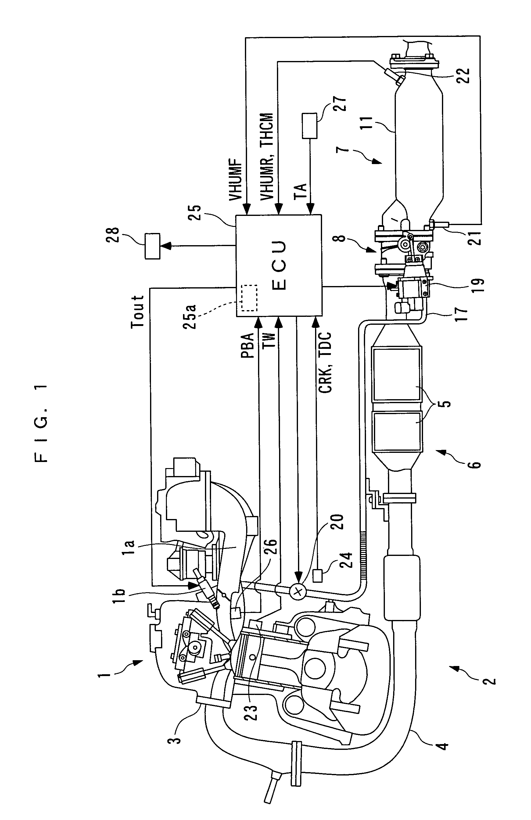
[0024] In the following, a preferred embodiment of the present invention will be described in detail with reference to the accompanying drawings. FIG. 1 illustrates an internal combustion engine 1 which employs an adsorbent state determining apparatus according to one embodiment of the present invention. The internal combustion engine (hereinafter simply referred to the "engine") 1 is, for example, a four-cylinder four-cycle engine equipped in a vehicle, not shown. The engine 1 has an intake pipe 1a which is provided with an injector 1b associated with each cylinder, and a fuel injection time Tout of the injector 1b is controlled by an engine control unit (ECU) 25, later described.

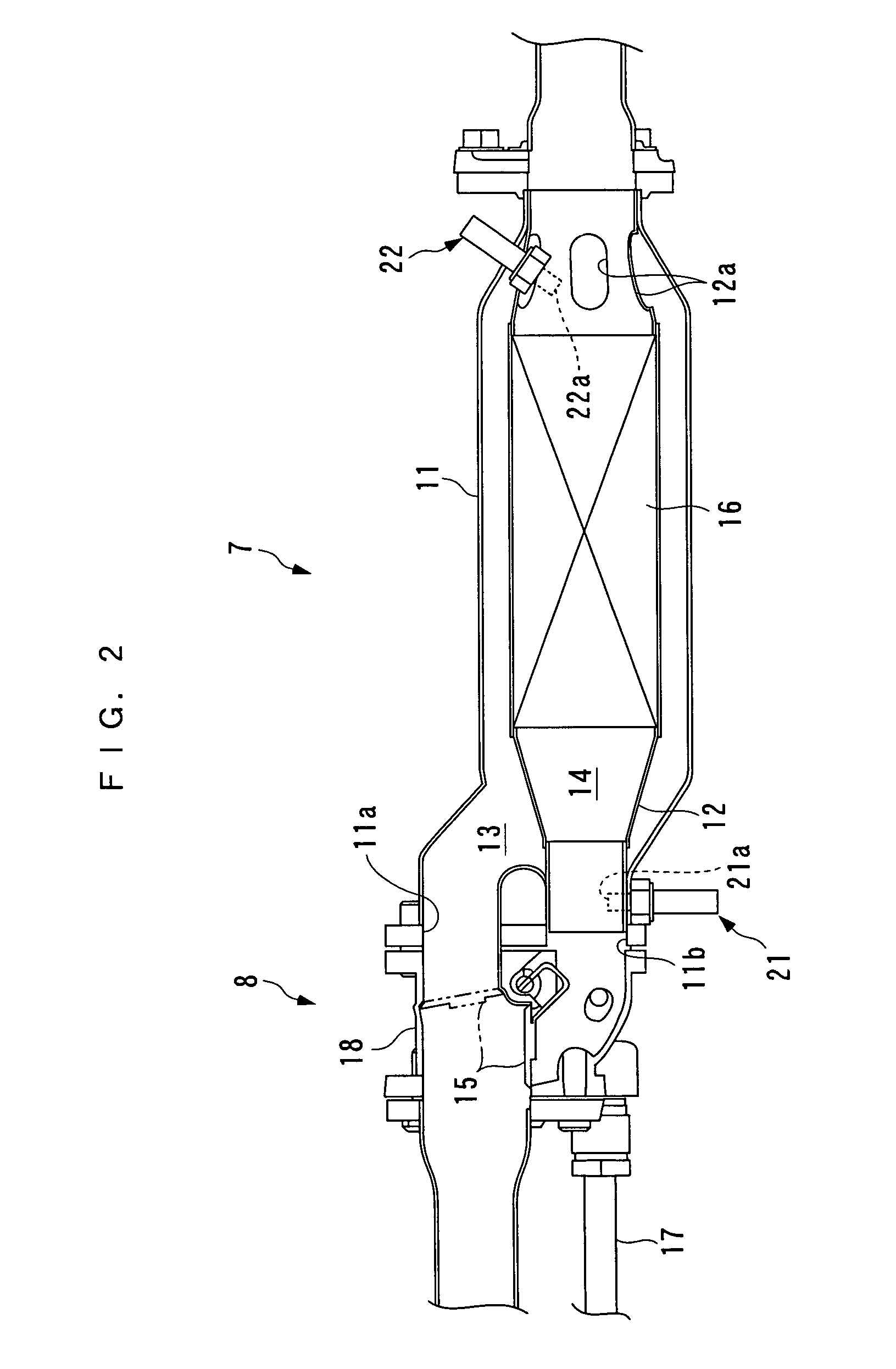
[0025] The engine 1 comprises an exhaust system 2 which has an exhaust pipe 4 connected to the engine 1 through an exhaust manifold 3. A catalyzer 6 having two three-way catalysts 5 for purifying exhaust gases, and a hydrocarbon adsorber 7 for adsorbing hydrocarbons are provided at intermediate locations i...


PUM

PropertyMeasurementUnit
Temperatureaaaaaaaaaa
Velocityaaaaaaaaaa
Humidityaaaaaaaaaa

Abstract

A hydrocarbon adsorbent state determining apparatus is provided for compensating the ability of a hydrocarbon adsorbent to adsorb moisture for fluctuations due to a change in the flow velocity of exhaust gases to accurately determine the state of the hydrocarbon adsorbent, including a deterioration thereof, irrespective of the change in the flow rate of exhaust gases. The hydrocarbon adsorbent state determining apparatus determines the state of a hydrocarbon adsorbent disposed in an exhaust system of an internal combustion engine for adsorbing hydrocarbons and moisture within exhaust gases. The hydrocarbon adsorbent state determining apparatus comprises a downstream humidity sensor for detecting the humidity of exhaust gases which have passed through the hydrocarbon adsorbent, a flow velocity parameter detector for detecting a flow velocity parameter indicative of a flow velocity of the exhaust gases, and an ECU for determining the state of the hydrocarbon adsorbent in accordance with the detected humidity of the exhaust gases and the flow velocity parameter.

Description

[0001] 1. Field of the Invention[0002] The present invention relates to a hydrocarbon adsorbent state determining apparatus for determining the state of an adsorbent, including a deterioration thereof, arranged in an exhaust system of an internal combustion engine for adsorbing hydrocarbons and moisture within exhaust gases.[0003] 2. Description of the Prior Art[0004] Some internal combustion engines are provided with an adsorbent for adsorbing hydrocarbons in exhaust gases upon starting. The adsorbent has, for example, zeolite on the surface such that hydrocarbons in exhaust gases introduce into pores of zeolite when they pass through the adsorbent, and are adsorbed by the adsorbent. The adsorbent desorbs the hydrocarbons once adsorbed thereby when the adsorbent is heated by exhaust gases to a predetermined temperature or higher (for example, 100-250.degree. C.), permitting the desorbed hydrocarbons to be recirculated to the internal combustion engine through an EGR pipe and the li...

Claims


Application Information

Patent Timeline
IPC IPC(8): F02D45/00B01D53/04F01N3/08F01N3/18F01N3/20F01N3/24
CPCY10S55/30B01D53/0454
Inventor UENO, MASAKIYAMAZAKI, HIDEHARUTAKAKURA, SHIROMIYAHARA, YASUYUKIENDO, TETSUO
Owner HONDA MOTOR CO LTD
Learn More