Motor control apparatus

a motor control and motor technology, applied in the direction of program control, dynamo-electric converter control, instruments, etc., can solve the problems of motor uncontrollability, motor cannot be driven normally, motor cannot continue normal feedback control, etc., to reduce driving torque, reduce motor size, and increase reliability

Active Publication Date: 2004-01-15
DENSO CORP
View PDF15 Cites 65 Cited by
  • Summary
  • Abstract
  • Description
  • Claims
  • Application Information

AI Technical Summary

Benefits of technology

0015] As described above, when an abnormality is detected in one of the at least two systems of drive coils and drive circuits, an open-loop control is performed by using the drive coil and the drive circuit of the remaining system that operate normally, whereby the rotor can be driven at a low speed. Therefore, even if an abnormality has occurred in the d

Problems solved by technology

As a result, the rotor may stop or rotate in reverse to cause a state that the feedback control cannot be continued normally.
In such a case, the motor becomes uncontrollable.
Further, if a disconnection occurs in the drive coil of a motor or their drive circuit fails, the motor cannot be driven normally.

Method used


Image

  • Motor control apparatus
  • Motor control apparatus
  • Motor control apparatus

Examples


first embodiment

[0090] A first embodiment in which the present invention is applied to a position switching device of a vehicle will be hereinafter described with reference to FIGS. 1-48.

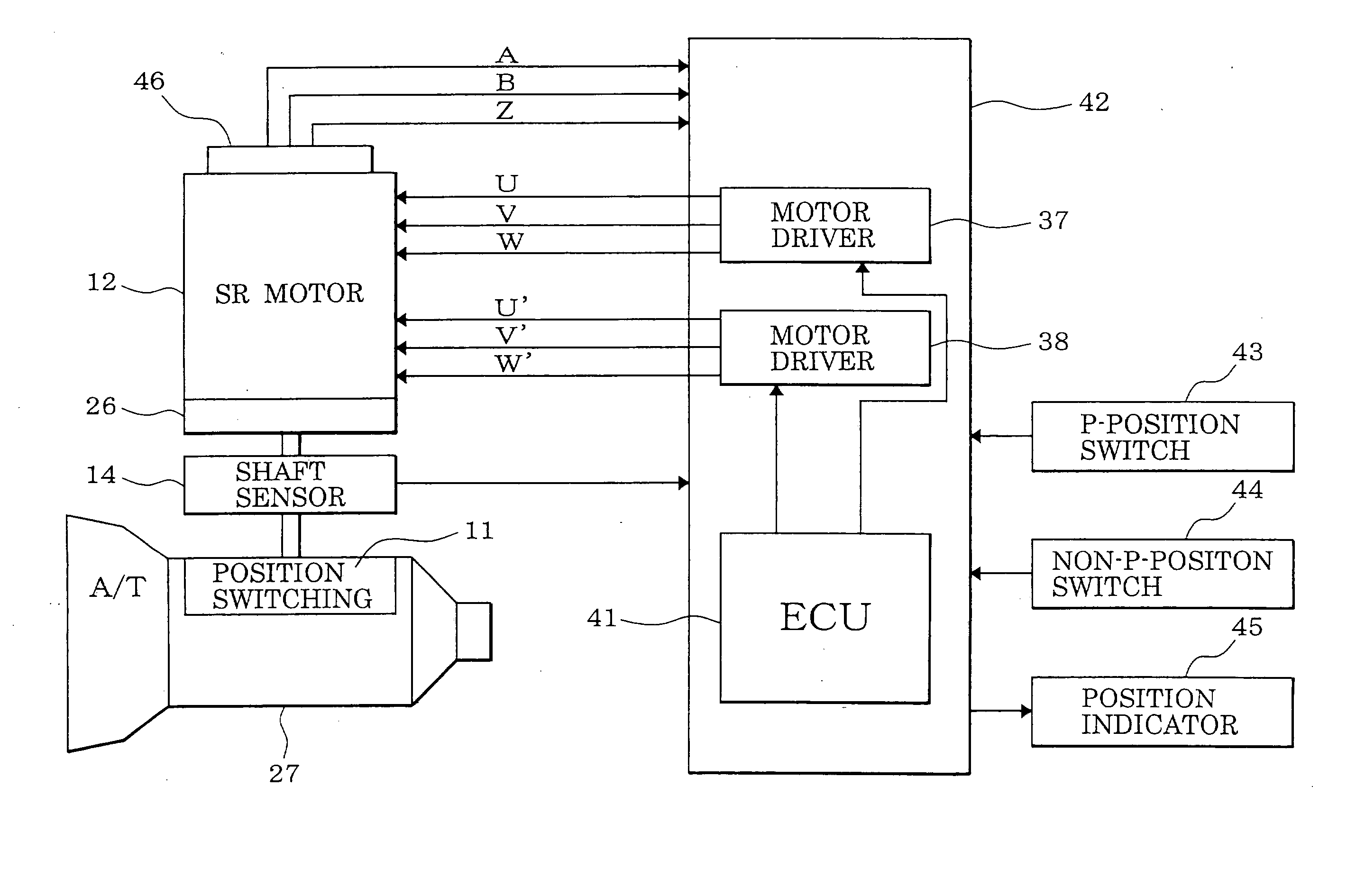
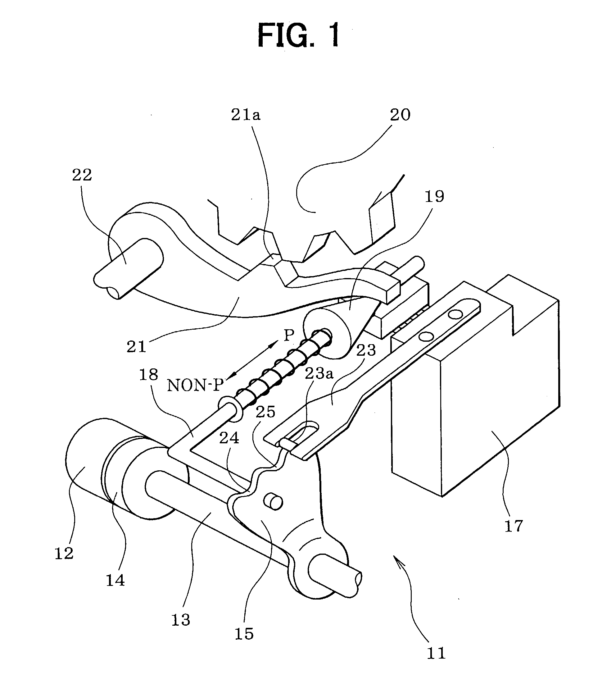
[0091] First, the configuration of a position switching mechanism 11 will be described with reference to FIG. 1. A motor 12 as a drive source of the position switching mechanism 11 is a switched reluctance motor, for example, incorporates a speed-reducing mechanism 26 (see FIG. 4), and is equipped with an output shaft sensor 14 for detecting a rotation position of the output shaft 13 of the speed-reducing mechanism 26. A detent lever 15 is fixed to the output shaft 13.

[0092] An L-shaped parking rod 18 is fixed to the detent lever 15. A conical body 19 that is provided at the tip of the parking rod 18 is in contact with a lock lever 21. The lock lever 21 is moved in the vertical direction in accordance with the position of the conical body 19 and thereby locks or unlocks a parking gear 20. The parking gear 20 is att...

second embodiment

[0505] A second embodiment of the invention will be described below with reference to FIGS. 71-75.

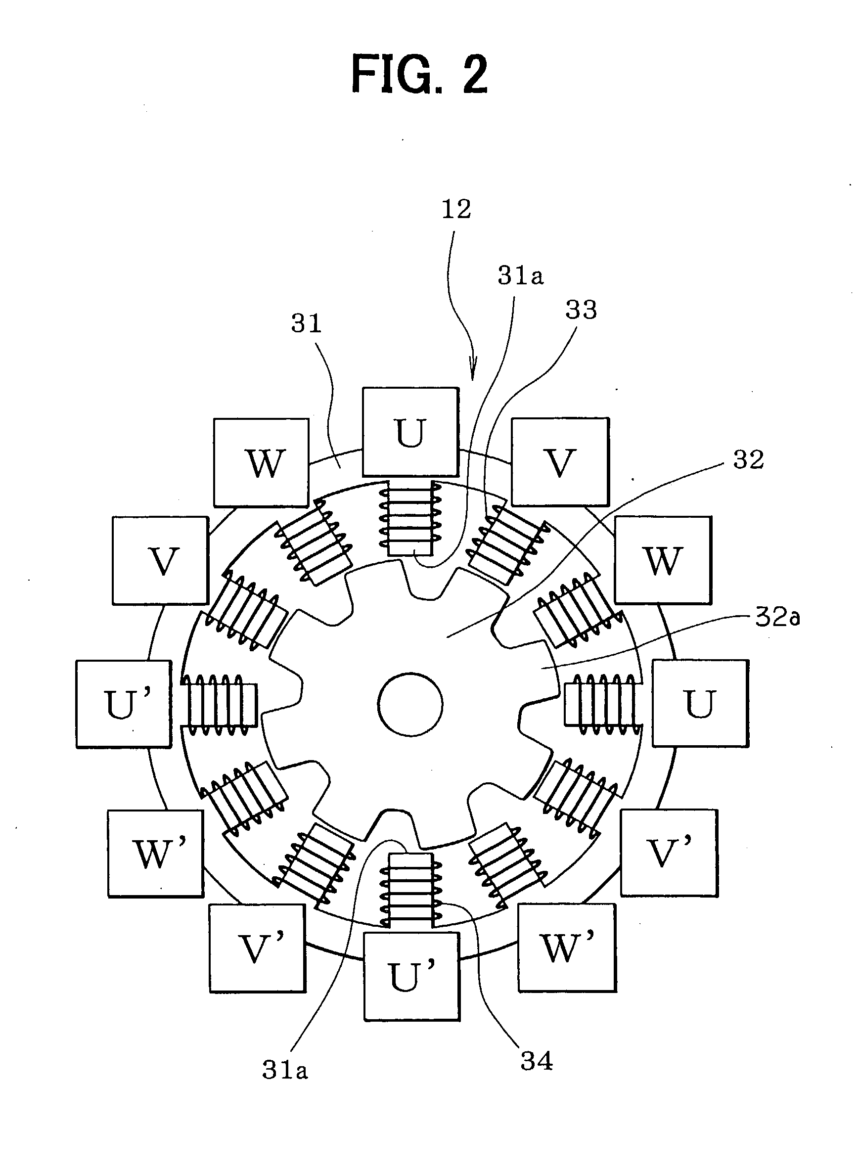
[0506] As shown in FIG. 72, while the SR motor 12 rotates, A-phase signal pulses and B-phase signal pulses are output alternately from the encoder 46 in synchronism with the rotation of the rotor 32 and a Z-phase signal pulse is output from the encoder 46 every time current supply is effected for all the phases around and the rotor 32 rotates by 45.degree.. The reference rotation positions of the rotor 32 can be detected correctly by using Z-phase signal pulses. Therefore, whether the rotation position of the rotor 32 and the current supply phase (i.e., encoder count) are in a correct relationship can be checked by determining whether a current supply phase (i.e., an encoder count) that is selected when a Z-phase signal pulse is output coincides with a current supply phase (i.e., an encoder count) corresponding to a reference rotation position of the rotor 32. If a deviation is found, a...

third embodiment

[0555] A third embodiment of the invention will be described below with reference to FIGS. 76-81.

[0556] [Open-Loop Control]

[0557] An open-loop control routine shown in FIGS. 76-78 is activated every predetermined time (e.g., every 1 ms). Upon activation of this routine, at step 3931, it is determined whether the open-loop control execution flag Xopen is "on." If the flag Xopen is "off," this routine is finished without executing the remaining steps.

[0558] On the other hand, if the open-loop control execution flag Xopen is "on," the routine proceeds from step 3931 to step 3932, where the count Top of a time counter that counts time is incremented. At the next step 3933, it is determined whether the count Top of the time counter has become greater than or equal to a current supply time tm of a current supply phase. If the time count Top is smaller than the current supply time tm, this routine is finished without executing the remaining steps. With this measure, step 3934 and the follo...


PUM


Abstract

Presence/absence of a failure in a feedback control system of a motor is monitored. When a failure is detected in the feedback control system, the motor is driven by switching to an open-loop control. During the open-loop control, the motor is rotated by sequentially switching the motor current supply phase without feeding back encoder count information. The position count is incremented or decremented every time the current supply phase is switched. When the position count has reached a target count, it is determined that the rotor has reached a target position, whereupon the open-loop control is finished.

Description

CROSS REFERENCE TO RELATED APPLICATION[0001] This application is based on and incorporates herein by reference Japanese Patent Applications No. 2002-199469 filed on Jul. 9, 2002, No. 2002-207557 filed on Jul. 16, 2002, No. 2002-207558 filed on Jul. 16, 2002, and No. 2002-207559 filed on Jul. 16, 2002.FIELD OF THE INVENTION[0002] The present invention relates to a motor control apparatus for rotationally driving (rotating) the rotor of a motor to a target position by detecting the rotation position of the rotor on the basis of the count of a pulse signal of an encoder and sequentially switching the current supply phase of the motor.BACKGROUND OF THE INVENTION[0003] Brushless motors such as switched reluctance motors are increasingly demanded recently because they are inexpensive and simple in structure. Those motors incorporate an encoder for outputting a pulse signal in synchronism with the rotation of the rotor, which is rotated by sequentially switching the current supply phase by...

Claims


Application Information

Patent Timeline
IPC IPC(8): G05B19/4062H02P6/12
CPCG05B19/4062H02P6/12G05B2219/42322G05B2219/42287
Inventor KAMIO, SHIGERUFUJIKI, KENICHI
Owner DENSO CORP
Why Eureka
Try Eureka