
Packaging laminate for a retortable packaging container

a packaging container and laminate technology, applied in the field of packaging laminates, can solve the problems of losing mechanical strength and configurational stability of packaging containers, losing both mechanical strength and configurational stability, and the desired tightness properties of packaging containers, so as to achieve the effect of retaining mechanical strength and configurational stability, and losing tightness properties

Inactive Publication Date: 2004-02-05
TETRA LAVAL HLDG & FINANCE SA
View PDF24 Cites 14 Cited by
  • Summary
  • Abstract
  • Description
  • Claims
  • Application Information

AI Technical Summary

Benefits of technology

[0008] A further object of the present invention is to provide a packaging laminate of the type described by way of introduction for a packaging container which may be heat treated in a retort, without risk of delamination and consequential loss of mechanical strength and configurational stability, as well as lost tightness properties.
[0014] As was mentioned previously, a shelf life extending heat treatment is generally carried out at a treatment temperature within the range of 70-130.degree. C. and during such a total treatment time that the packed food is given the desired combination of high Fo-value and low Co-value. The layer of lamination or sealing agent for bonding the gas barrier to the core layer in the packaging laminate according to the present invention should thus have a melting point of above 130.degree. C. in order efficiently to eliminate the risk of delamination of the packaging laminate during normal heat treatment of the packaging laminate at an optional treatment temperature within the range of 70-130.degree. C.

Problems solved by technology

A packaging container of the known packaging laminate generally functions well in a normal heat treatment in a retort, but, on the other hand, problems may not seldom arise in such cases when the heat treatment is carried out at an extremely high treatment temperature within the range of 70-130.degree. C. and / or during an extremely long treatment time, even at a relatively low treatment temperature within this range.
For example, it has proved that the internal bonding strength between the layers included in the packaging laminate have a tendency to become weakened, and that this weakening may even be so great that the packaging laminate, at excessively high treatment temperatures, delaminates, whereby the packaging container loses both its mechanical strength and configurational stability, as well as its desired tightness properties.

Method used


Image

  • Packaging laminate for a retortable packaging container
  • Packaging laminate for a retortable packaging container

Examples


Embodiment Construction

[0021] It should be observed that the present invention is not restricted to the specific preferred embodiments which are shown on the Drawing, and that numerous alterations and modifications of the packaging laminate and the retortable packaging container are obvious to a person skilled in the art without departing from the inventive concept as this is defined in the appended Claims.

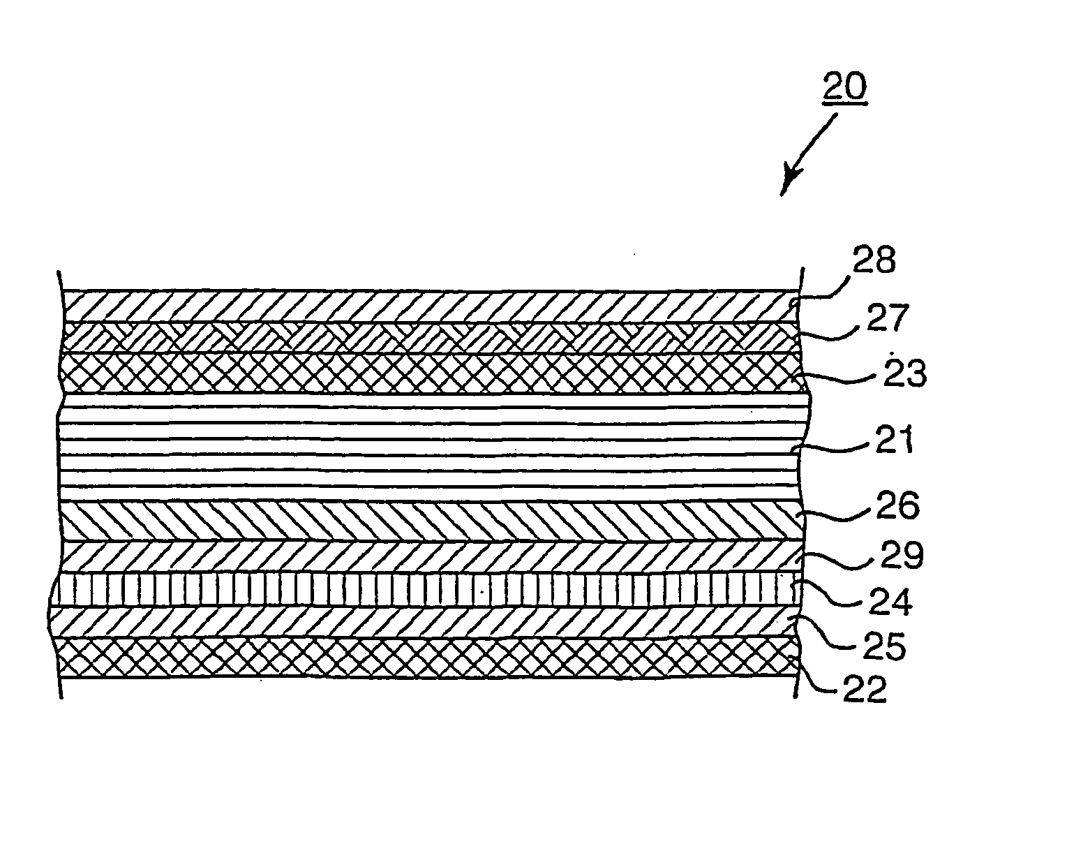
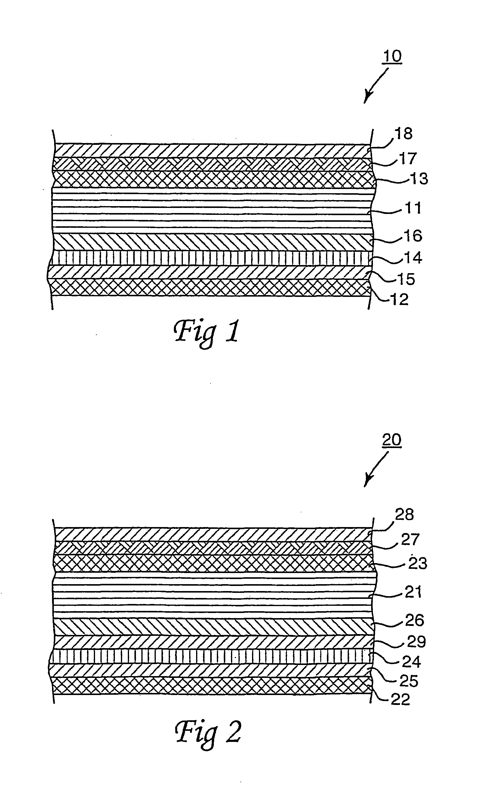
[0022] FIG. 1 thus shows a schematic cross section of the packaging laminate according to a first preferred embodiment of the present invention. The packaging laminate, carrying the generic reference numeral 10, has a core layer 11 and outer, liquid-tight coatings 12 and 13 on both sides of the core layer 11.

[0023] The packaging laminate 10 further has a gas barrier 14 between the core layer 11 and the one liquid-tight coating 12.

[0024] Between the liquid-tight coating 12 and the gas barrier 14, there is disposed a layer 15 of a binder or adhesive by means of which the liquid-tight coating 12 is partial...


PUM

PropertyMeasurementUnit
melting pointaaaaaaaaaa
temperatureaaaaaaaaaa

Abstract

The disclosure relates to a packaging laminate for a retortable packaging container comprising a core layer (11), outer, liquid-tight coatings (12 and 13) and a gas barrier (14) disposed between the one coating (12) and the core layer (11). Between the gas barrier (14) and the core layer (11), there is a layer (16) of a lamination or sealing agent of such a nature that the lamination or sealing agent has a melting point which is higher than the maximum temperature to which the retortable packaging container is to be subjected during a normal heat treatment in a retort. The lamination or sealing agent in the layer (16) may, for example, be a polypropylene with a melting point of above 130° C.

Description

[0001] The present invention relates to a packaging laminate for a retortable packaging container or carton comprising a core layer, outer, liquid-tight coatings and a gas barrier disposed between the core layer and the one outer coating. The present invention also relates to a retortable packaging container or carton of the packaging laminate.[0002] A packaging laminate of the above-described type is previously known from, for example, international patent application carrying publication number WO 97 / 02140. The known packaging laminate has a rigid, but foldable core layer of paper or paperboard and outer, liquid-tight coatings of humidity and heat-resistant thermoplastic material on both sides of the core layer. In order to impart to the known packaging laminate tightness properties also against gases, in particular oxygen gas, the packaging laminate moreover has a gas barrier, for example an aluminium foil (Alifoil) disposed between the core layer and the one outer coating.[0003]...

Claims


Application Information

Patent Timeline
Patent Type & Authority Applications(United States)
IPC IPC(8): B32B7/12B65D81/24B32B27/00B32B27/10B32B27/32B65D65/40
CPCB32B7/12B32B27/32Y10T428/1383Y10T428/1303Y10T428/1379Y10T428/3188Y10T428/31703Y10T428/31891Y10T428/31692Y10T428/31855
Inventor ANDERSSON, THORBJORNKJELGAARD, TOMLETH, IB
Owner TETRA LAVAL HLDG & FINANCE SA
Learn More