Method for the production of a carbon fiber-based reinforcing element for tires

a technology of carbon fiber and reinforcing elements, which is applied in the direction of tires, vehicle components, textiles and paper, etc., can solve the problems of poor fatigue behavior, low tensile strength of fibers, and inability to allow the core fibers to be sufficiently impregnated

Inactive Publication Date: 2004-03-04
SOVOUTRI SOC VOULTAINE DE TRANSFORMES INDS
View PDF21 Cites 29 Cited by
  • Summary
  • Abstract
  • Description
  • Claims
  • Application Information

AI Technical Summary

Benefits of technology

[0017] In practice, by opening the fibers during the impregnation step, the lubricating properties of the impregnation bath are put to good use, thus avoiding the risks of filament breakage.
[0034] Advantageously, for the carbon fiber to be used in certain articles such as, in particular, timing belts, it may prove advantageous for the method according to the invention to furthermore include an additional step of impregnating the cabled or twisted fiber with an adhesive in a solvent medium. This step makes it possible to obtain an additional layer covering the fiber. This additional layer, forming a ring around the fiber, is particularly advantageous for ensuring good adhesion to certain types of rubber, such as acrylonitrile (NBR), hydrogenated acrylonitrile (HNBR), carboxylated hydrogenated acrylonitrile (X-HNBR), vulcanizable hydrogenated acrylonitrile (ZSC), chlorosulfonated polyethylene (CSM), alkylated chlorosulfonated polyethylene (ACSM) and ethylenepropylene-diene monomer (EPDM).

Problems solved by technology

This results in a low tensile strength of the fiber and, in dynamic operation, many fractures of the internal filaments are observed, hence poor fatigue behavior.
Unfortunately, this technique does not allow the core fibers to be sufficiently impregnated, and the tensile strength problems already mentioned remain.
Such splaying must be done under sufficient tension for the filaments to spread out with respect to one another, but this tension must not be too high as the filaments cannot spread out further, and the risks of filament fracture increase.
The tension with which the fiber (12) from the creel is paid out must be high enough to allow the fibers to open during the splaying that follows, but must not exceed a limit above which the fiber remains grouped together and even runs the risk of certain filaments breaking.

Method used


Image

  • Method for the production of a carbon fiber-based reinforcing element for tires
  • Method for the production of a carbon fiber-based reinforcing element for tires
  • Method for the production of a carbon fiber-based reinforcing element for tires

Examples


example 2

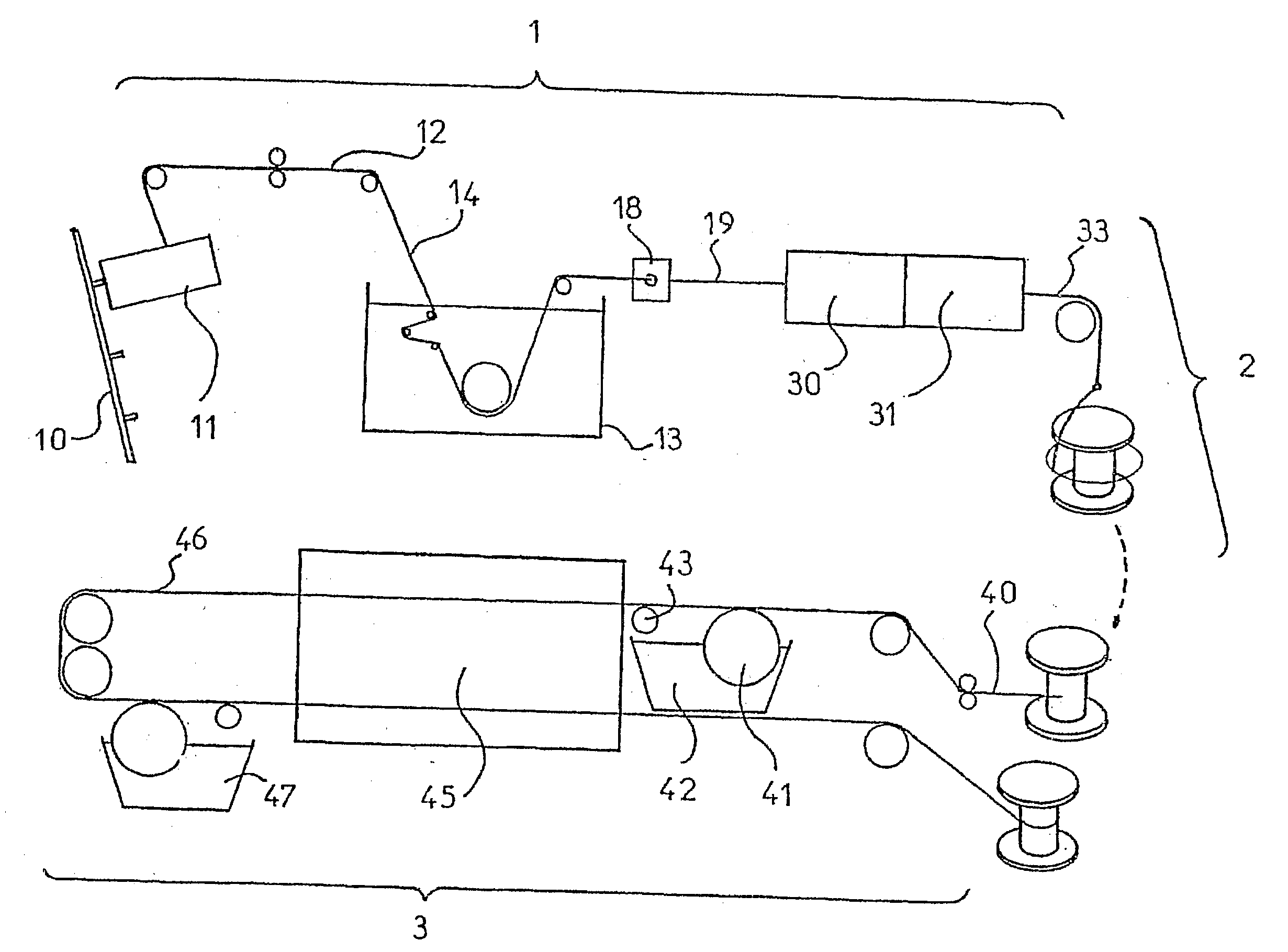
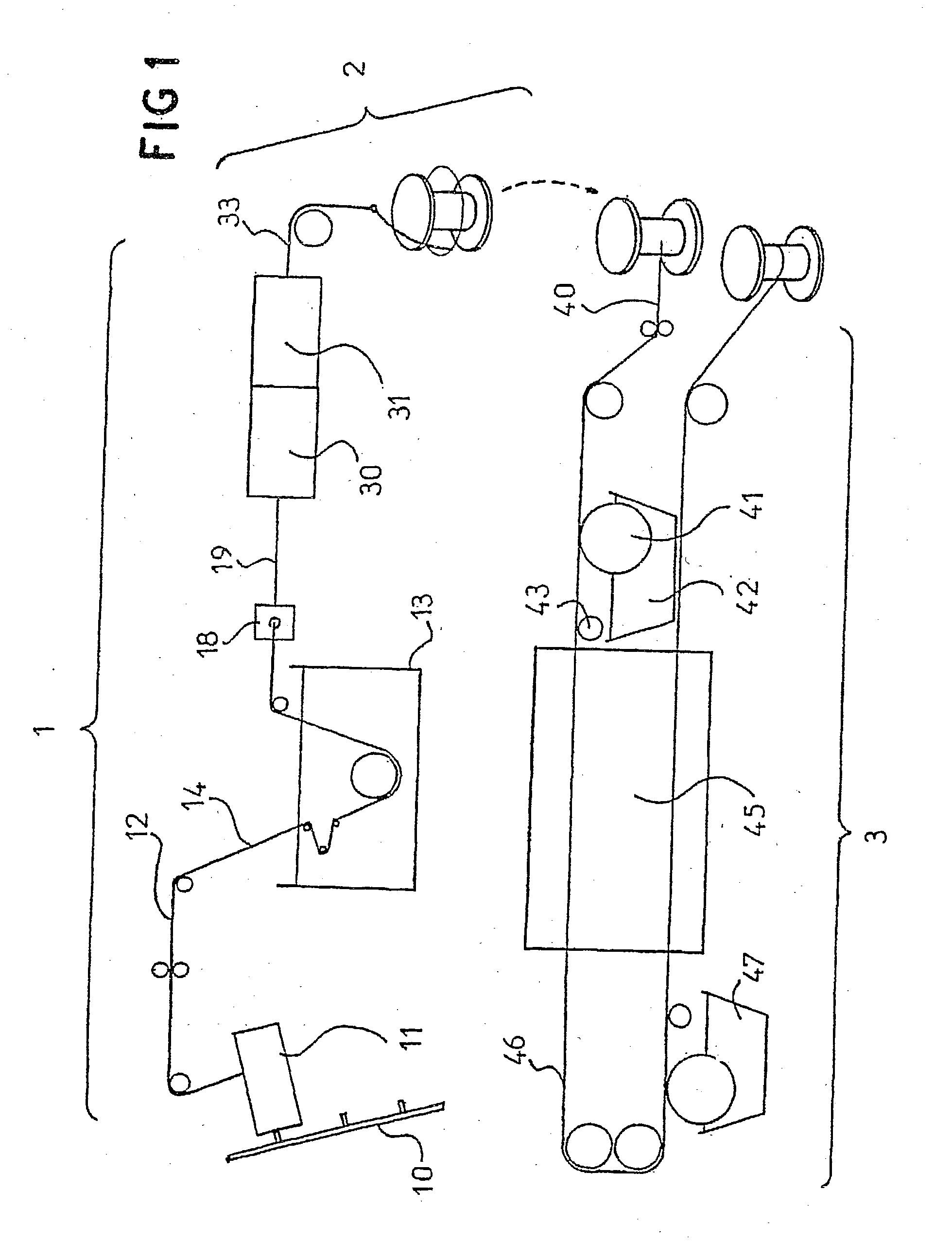
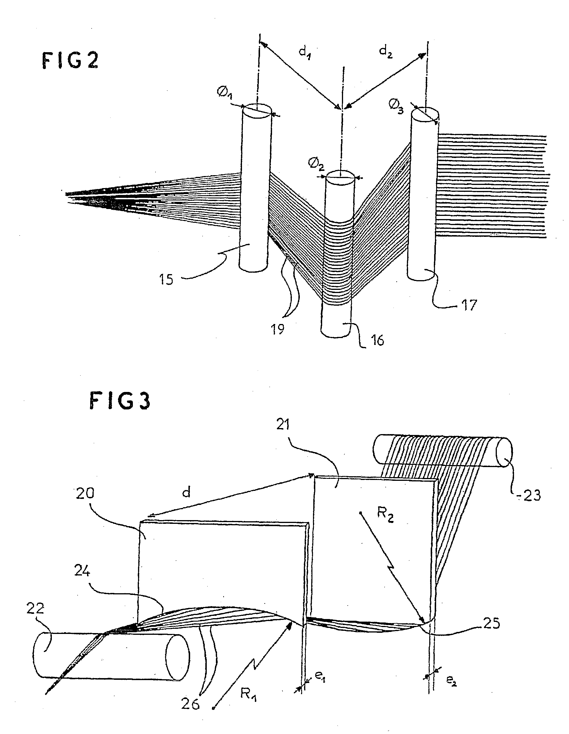
[0081] A fiber sold by Toray under the reference TORAYCA-700 GC 4 12K, corresponding to a yarn of 800 tex overall linear density and comprising 12 000 filaments, was used. The tension with which the fiber was delivered from the creel was 45 grams. Each fiber was splayed out by three bars 1 millimeter in diameter arranged in an isosceles triangle with a base of 20 mm and a height of 8 mm placed a few centimeters before the impregnation tank, and two bars 1 mm in diameter separated by 34 mm immersed in the impregnation tank.

[0082] The impregnation solution was the same as that of example 1, with a solids content adjusted to 330 g / kg.

[0083] The speed of the fibers through the impregnation bath was about 20 meters per minute. On leaving the impregnation bath, the yarn was passed through a die 1.1 millimeters in diameter and the fiber then passed through a curing oven, again at a speed of 20 meters per minute. The temperature of the oven was 280.degree. C. The length of the oven was 3 me...

example 3

[0086] A fiber sold by Toray under the reference TORAYCA-400 HB 40D 6K, corresponding to a yarn of 400 tex overall linear density and comprising 6000 filaments, was used. The tension with which the fiber was delivered from the creel was 50 grams. Each fiber was splayed out by three bars 1 millimeter in diameter arranged in an isosceles triangle with a base of 20 mm and a height of 8 mm placed a few centimeters before the impregnation tank, and two bars 1 mm in diameter separated by 34 mm immersed in the impregnation tank.

[0087] The impregnation solution was obtained by mixing:

[0088] a first part A composed of:

[0089] 36 liters of deionized water,

[0090] 4 liters of 20.5% aqueous ammonia of Vaissire Favre brand,

[0091] 10 kilograms of PENACOLITE of reference R2170 (75% concentration) sold by Indspec Chemical Corp.,

[0092] 27.2 kilograms of 41% urea of Vaissire Favre brand;

[0093] a second part B composed of:

[0094] 36 liters of deionized water,

[0095] 286 kilograms of Zetpol B latex sold by...

example 4

[0110] A fiber identical to that of example 3 was used. The tension with which the fiber was delivered from the creel was 30 grams. Each fiber was splayed out by two bars 1 millimeter in diameter, separated by 39 mm, that were immersed in the coating tank.

[0111] The impregnation solution was the same as that used in example 3, with a solids content adjusted to 330 g / kg.

[0112] The speed of the fibers through the impregnation bath was about 20 meters per minute. On leaving the impregnation bath, the yarn was passed through a die 0.81 millimeters in diameter and the fiber then passed through a curing oven, again at a speed of 20 meters per minute; the temperature of the oven was 180.degree. C. The length of the oven was 3 meters. On leaving the oven, the fiber had a coating, corresponding to the amount of cured impregnation solution material, representing approximately 19.8% by dry weight of the yarn.

[0113] The fibers thus obtained were then twisted as in example 3, but under a tension...


PUM

PropertyMeasurementUnit
linear densityaaaaaaaaaa

Abstract

A method for the production of a multifilament carbon fibre-based longitudinal reinforcing element, designed to be incorporated in a rubber-based item. Said method comprises the following steps, whereby untwisted carbon fibres are plunged into an impregnating bath contained a solution of resorcinol-formaldehyde resin and rubber latex, the impregnated fibres are then dried and the dried fibres are subsequently twisted. The inventive method is characterised by the fact that it also comprises a step, during the impregnation step, consisting in opening out the carbon fibres by spreading out the constituent filaments thereof in such a way that each fibre has an increased surface area on which the impregnation can be performed.

Description

[0001] The invention relates to the field of the textile industry. More precisely, it relates to the sector concerned with the manufacture of reinforcing elements to be incorporated into rubber-based articles, such as automobile belts, and hoses or tires. It relates more specifically to a process for treating a carbon fiber allowing the properties of this fiber to be optimized, especially in terms of elongation and tensile strength.[0002] In the rest of the description, the term "carbon fiber" will be used to denote a continuous multifilament yarn of carbon.PRIOR ART[0003] As is known, many rubber-based articles, such as belts or tires, are subjected to high tensile stresses. This is why they are generally reinforced with glass or carbon strands embedded in the rubber.[0004] It has been proposed in document U.S. Pat. No. 6,077,606 to use carbon fibers as reinforcing elements for tires.[0005] The fibers described in that document are obtained by a process involving several steps. In ...

Claims


Application Information

Patent Timeline
Patent Type & Authority Applications(United States)
IPC IPC(8): B65H51/005B65H57/16C08J5/06D02G3/40D02G3/48B60C9/00D02J1/18D06M15/233D06M15/31D06M15/356D06M15/41D06M15/423D06M15/693D06M101/40
CPCB29B15/125B65H51/005B65H57/16B65H2701/31C08J5/06C08J2321/00Y10T428/2918D06M15/233D06M15/31D06M15/356D06M15/41D06M15/423D02J1/18
Inventor TONON, CORINNE
Owner SOVOUTRI SOC VOULTAINE DE TRANSFORMES INDS
Why Eureka
Try Eureka