Projection system for EUV lithography
- Summary
- Abstract
- Description
- Claims
- Application Information
AI Technical Summary
Problems solved by technology
Method used
Image
Examples
Embodiment Construction
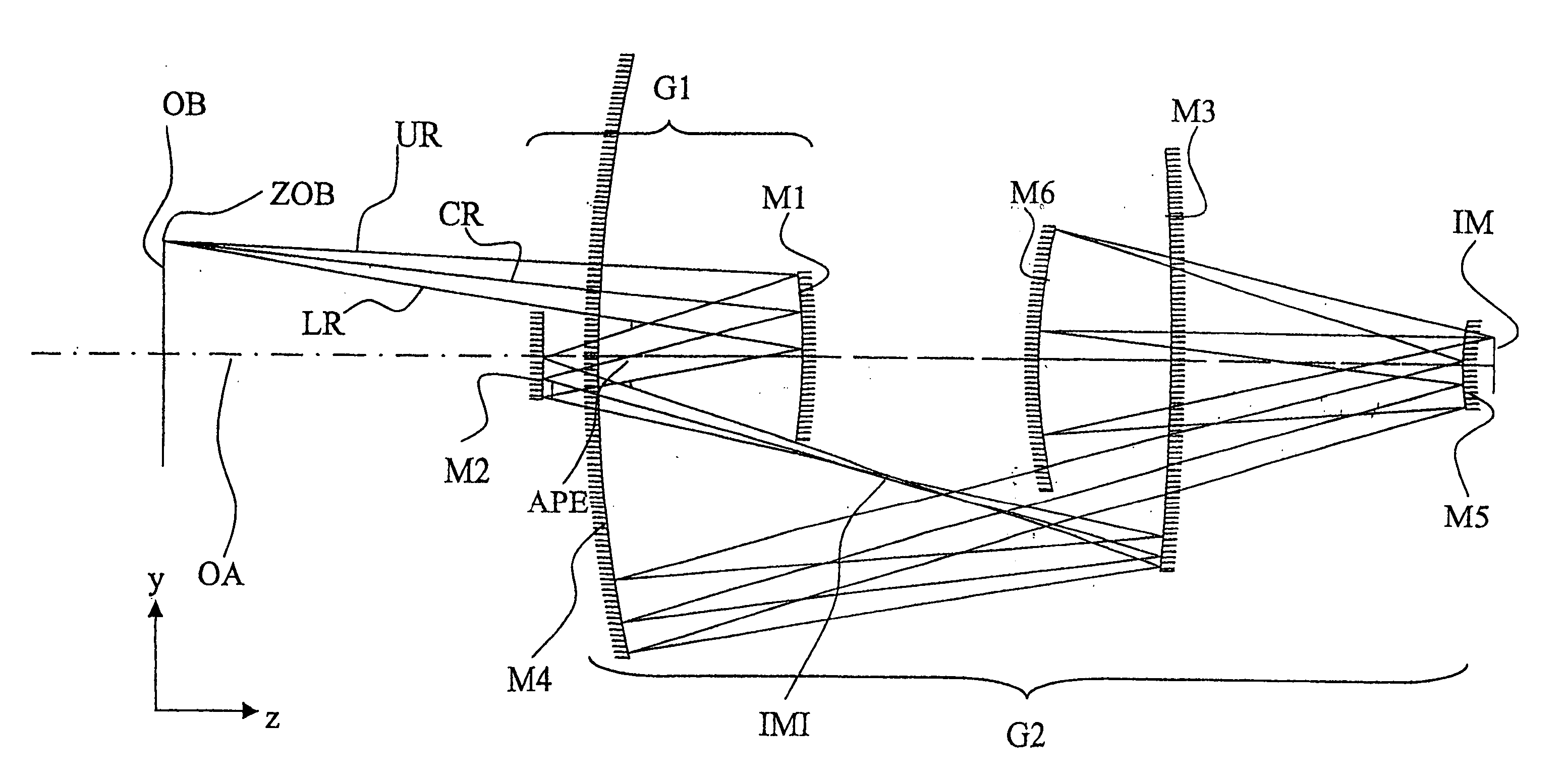
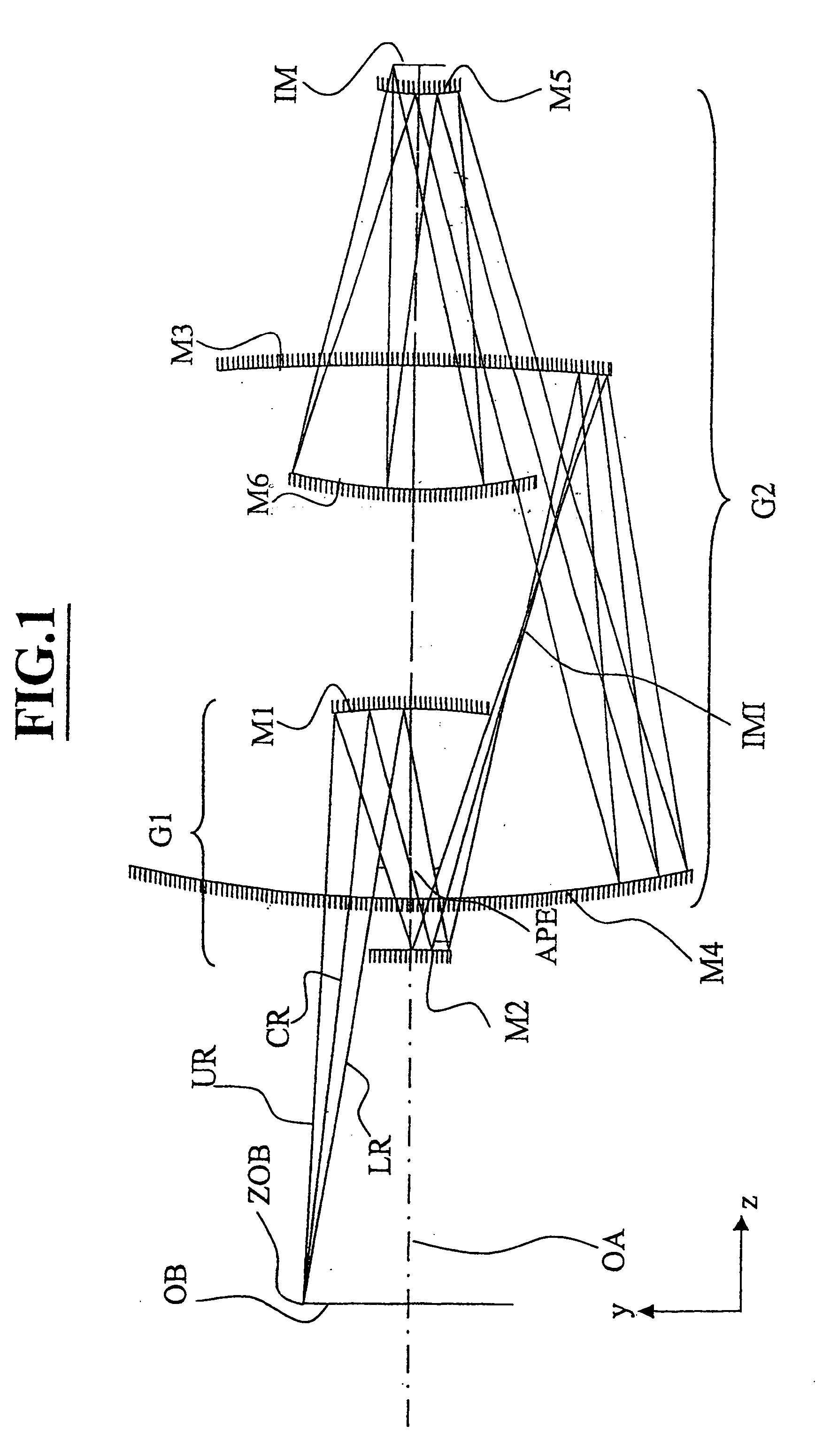
[0073] FIG. 1 schematically illustrates a first preferred embodiment, and, taking in conjunction with Table 1 and Table 2, provides an illustrative, exemplary description of this embodiment. Light impinges on an object OB, e.g. a reflective mask or a reticle, from an illumination source and is directed to concave mirror M1 after which it reflects from the mirror and passes through a physically accessible aperture stop APE that is located between mirror M1 and mirror M2. This aperture stop APE is a substantial distance from the first concave mirror M1 and, likewise, this aperture stop APE is located a substantial distance from convex mirror M2. After the illumination reflects off convex mirror M2, the light comes to a focus at an intermediate image IMI that is located in close proximity to concave mirror M3. From mirror M3 the illumination is directed toward concave mirror M4 where the light is nearly collimated and directed toward convex mirror M5. Upon reflection from mirror M5, th...
PUM
 Abstract
Description
Claims
Application Information
 - R&D
- Intellectual Property
- Life Sciences
- Materials
- Tech Scout
- Unparalleled Data Quality
- Higher Quality Content
- 60% Fewer Hallucinations
Browse by: Latest US Patents, China's latest patents, Technical Efficacy Thesaurus, Application Domain, Technology Topic, Popular Technical Reports.
© 2025 PatSnap. All rights reserved.Legal|Privacy policy|Modern Slavery Act Transparency Statement|Sitemap|About US| Contact US: help@patsnap.com


