Drywall texture gun

a texture gun and drywall technology, applied in the field of texture guns, can solve the problems of difficult cleaning, time and cost, and prior art machines designed for applying lightweight acoustic materials typically do not have the power to deliver heavier texture materials, and achieve the effects of quick and easy cleaning, simple replacement of any of the components, and easy assembly and disassembly

Inactive Publication Date: 2004-05-13
ANTONUCCI LOUIS A
View PDF7 Cites 40 Cited by
  • Summary
  • Abstract
  • Description
  • Claims
  • Application Information

AI Technical Summary

Benefits of technology

0008] The drywall texture gun of the present invention further comprises a hollow body connected to the first end of the chamber spray head. A source of compressed air, either a hand pump or a compressed air gun is connected to the second end. A nozzle seat is joined to the chamber spray head and adjustably supports the nozzle. The tube has a dimension smaller than a gauge of the nozzle seat, such that the compressed air can flow from the chamber spray head to the nozzle. The chamber spray head has an opening at a sidewall thereof allowing the tube to extend to the texture supply. The opening is larger than a dimension of the tube, such that the compressed air can flow from the chamber spray head in to the texture supply. The outlet has a protruded structure at a perimeter thereof to restrict the outlet in the nozzle, and at least one hole at a perime

Problems solved by technology

Therefore, prior art machines for spraying particulate texture material normally have sufficient power to deliver the lightweight acoustic material; however, such prior art machines are normally heavy, bulky and difficult to transport to different working environments.
In contrast, prior art machines designed for applying the lightweight acoustic material

Method used


Image

  • Drywall texture gun
  • Drywall texture gun
  • Drywall texture gun

Examples


Embodiment Construction

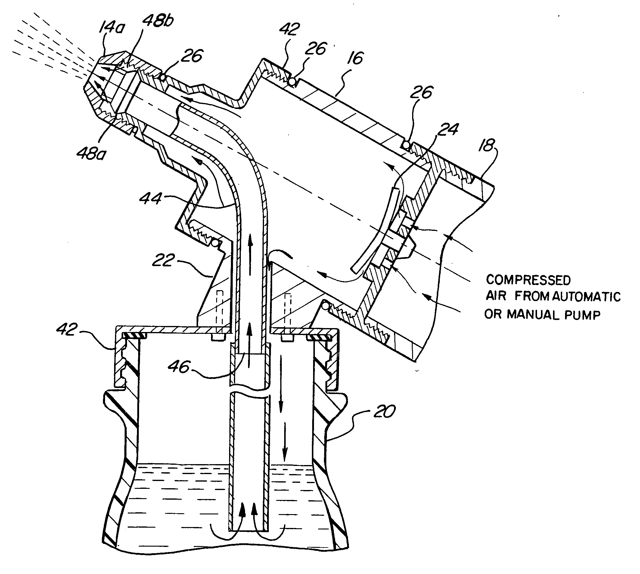
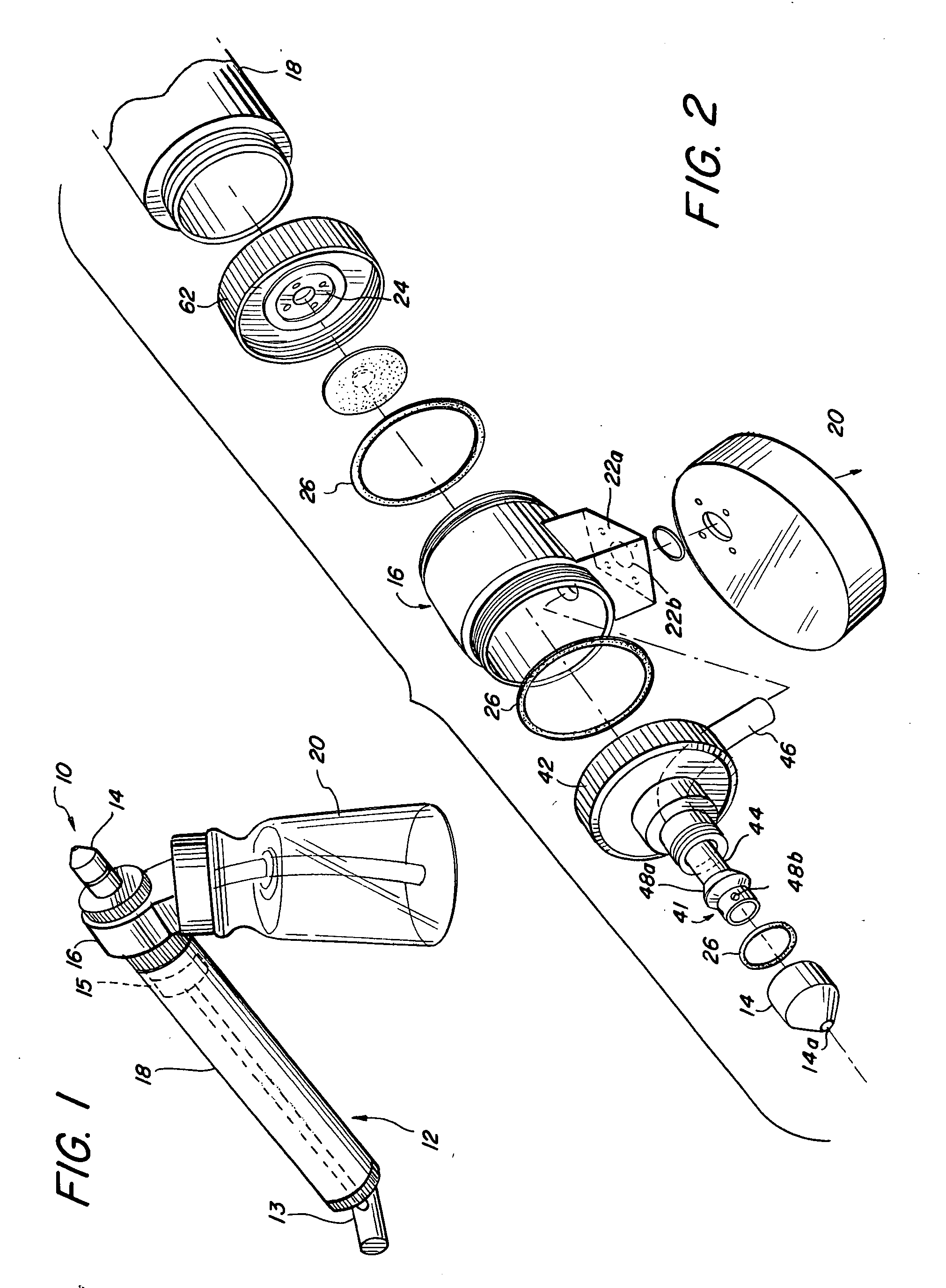
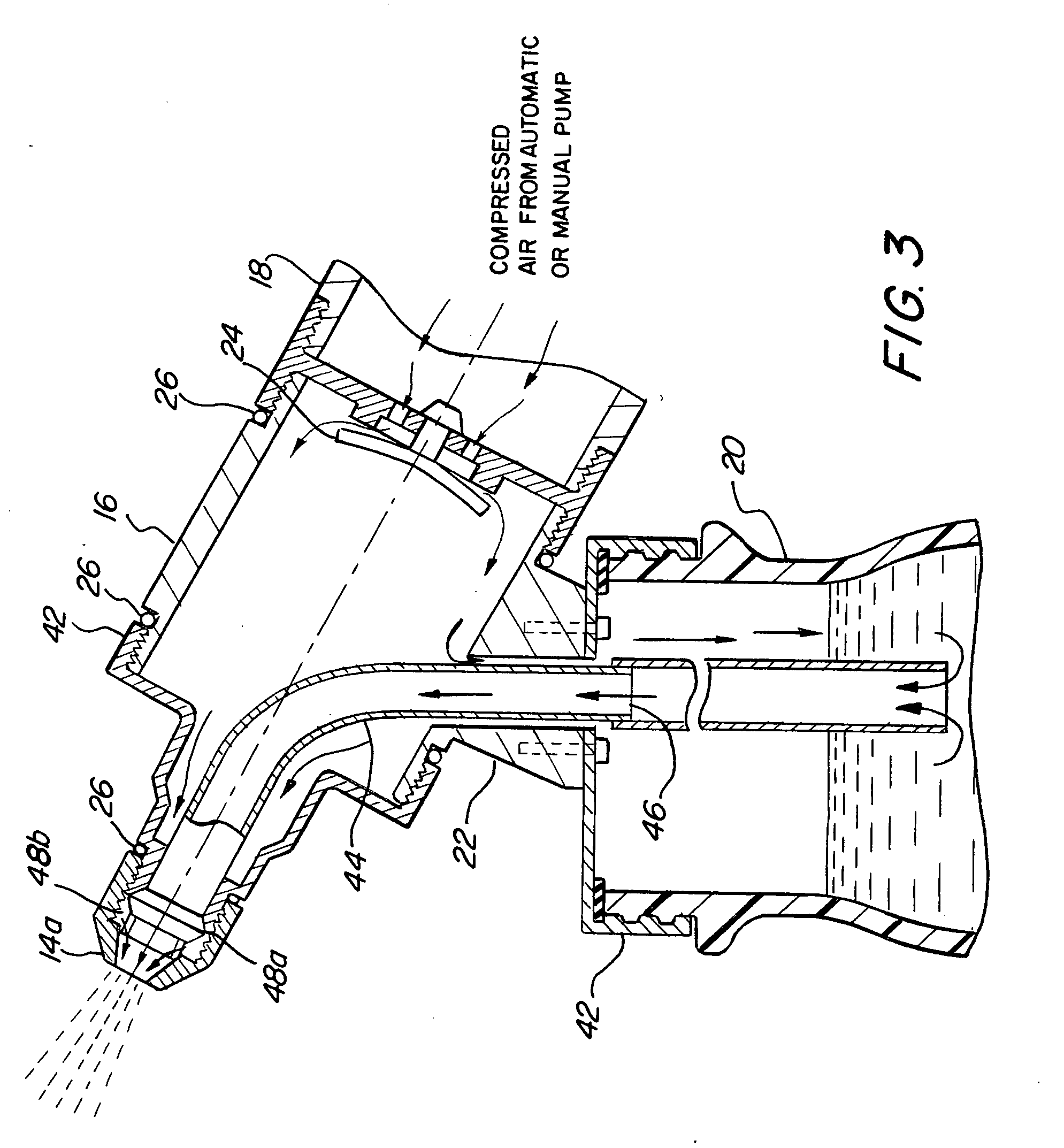
[0019] FIG. 1 is a perspective view showing the external feature of the texture gun 10 in one embodiment of the present invention. In this embodiment, the texture gun 10 is connected with a hand pump 12. It will be appreciated that one of ordinary skill in the art may also use other pressure supply structures such as an air compressor as set forth in the alternate embodiment shown in FIG. 6 to achieve the similar effect without exceeding the scope of the present invention. The texture gun 10 comprises a nozzle 14, a chamber spray head 16, and hand pump 12 having a hollow tubular body 18. The chamber spray head 16 is threadably connected to one longitudinal end of hollow tubular body 18, while a plunger 13 is connected to a piston 15 within hollow tubular body 18. The chamber spray head 16 is further connected to the nozzle 14 along its longitudinal axis and a texture supply 20 along the direction substantially perpendicular to the longitudinal axis. Preferably, one side of plunger 1...


PUM


Abstract

A drywall texture gun, having a chamber spray head with a one-way check valve installed at a first end thereof to allow compressed air flowing therein, a nozzle connected to a second end of the chamber spray head, and a supply tube extending across the chamber spray head with an inlet entering a texture supply and an outlet entering the nozzle. The outlet is restricted in the nozzle with an adjustable space to reciprocate responsive to the compressed air. Further, the outlet is so structured that the compressed air is introduced from the chamber spray head to adjust a pattern of a texture flowing therethrough. The inlet is so structured that the compressed air is able to flow from the chamber spray head to the texture supply to drive the texture into the tube. In an alternate embodiment, a compressed air gun is joined to the chamber spray head and includes a trigger assembly. An air bleed mechanism responds to the trigger during shut off to bleed off existing gun pressure.

Description

CROSS-REFERENCE OF RELATED APPLICATION[0001] This application is a continuation-in-part of copending application Ser. No. 10 / 206,546 filed Jul. 26, 2002 on behalf of the applicant of this application which is entitled DRYWALL TEXTURE GUN.FIELD OF THE INVENTION[0002] This invention relates generally to a texture gun, and more particularly, to a modular texture gun utilized for drywall finishing to achieve either an aesthetic effect or acoustical effect.BACKGROUND OF THE INVENTION[0003] In the construction of a building, texture is applied over a drywall to form a textured wall surface. A variety of textures may be used to acquire aesthetic or acoustical effects. For the purpose of acquiring the aesthetic effect, the material for texturing is often referred as "mud", which is typically heavy, thick and particulate. In contrast, the material for texturing the wall or ceiling with the acoustic effect is normally lightweight acoustic material. Therefore, prior art machines for spraying p...

Claims


Application Information

Patent Timeline
IPC IPC(8): B05B7/24E04F21/12
CPCB05B7/2416B05B7/2418B05B7/241B05B11/06E04F21/12B05B7/2437
Inventor ANTONUCCI, LOUIS A.
Owner ANTONUCCI LOUIS A
Why Eureka
Try Eureka