Optical fiber connector with ferrule radial orientation control

a technology of optical fiber connector and radial orientation control, which is applied in the direction of optics, instruments, optical light guides, etc., can solve the problems of optical power loss across the fiber connection, the cores of the two mating fibers in the connector unit failing to be perfectly aligned, and the connectors are subject to optical power loss, so as to minimize the loss caused by fiber core eccentricities

Inactive Publication Date: 2004-05-27
COMMSCOPE TECH LLC
View PDF6 Cites 34 Cited by
  • Summary
  • Abstract
  • Description
  • Claims
  • Application Information

AI Technical Summary

Benefits of technology

[0009] The present invention provides a method for establishing the rotational orientation of a ferrule containing an optical fiber connector to minimize losses caused by fiber core eccentricities. Specifically, the method of assembly in accordance with the present invention comprises (a) bonding a fiber within a ferrule having an end face such that an end of the fiber is presented at the end face; (b) positioning the ferrule within a housing; (c) preparing the end face of the ferrule such that the fiber secured therein is suitable for optical coupling to a mating component; (d) rotating the ferrule to a plurality of predetermined radial positions within the housing while measuring the power loss associated with each radial position to determine the optimal radial position; and (e) optionally polishing the end of the ferrule into the desired configuration after the optimum radial position is determined.
[0010] Accordingly, by rotating the ferrule and fiber simultaneously, any eccentricities that exist with respect to the fiber core can be orientated with respect to a particular area or segment of the connector. For example, in a connector with four predetermined positions, the mating surface of the connector is divided into four virtual quadrants. By tuning the connector in such a manner that any core eccentricities within the ferrule / fiber combination are orientated with respect to the same quadrant as the mating connector, more precise fiber alignment is achieved. This reduces insertion and Fresnel losses across the connection. Furthermore, because the beveled ends in an APC application are applied after the ferrule position has been selected, there is no concern of losing the complementing configuration.
[0011] Another aspect of the present invention is an optical fiber connector assembly that allows for post-assembly adjustment of the rotational position of the ferrule and fiber. In a preferred embodiment, the assembly comprises: (a) a ferrule sub-assembly comprising a ferrule containing an optical fiber having a front face, and a positioning member for maintaining the radial position of the ferrule sub-assembly in a selected position; (b) a front housing having a plurality of recesses in preselected radial positions for receiving the positioning; (c) a resilient member for urging the ferrule sub-assembly forward into the front housing such that the positioning member is held one of the recesses; and (d) a rear body to provide a back stop for the resilient member. Accordingly, the ferrule sub-assembly is capable of being rotated within the front housing and rear body, and is held into the selected position by having the resilient member urge the positioning member of the ferrule sub-assembly into one of the plurality of recesses formed inside the front housing.
[0013] Accordingly, by selecting the ferrule sub-assembly position that orientates the eccentricities into corresponding areas on two mating connectors, power loss is minimized. Furthermore, time and effort necessary to build a connector assembly is reduced because the connector can be assembled prior to rotational alignment and polishing of the fiber end. An additional advantage of this approach is that the connector may be assembled at a different time and place from the tuning and polishing, thus allowing for various levels of labor cost / skill to be used for the various operations.
[0014] Preferred embodiments use four or two predetermined ferrule positions; however, it is understood that any number of positions could be used for single mode PC and APC applications. The larger the number of positions available for selection, the more accurately the fiber cores can be aligned. A two position connector is optimum for PM applications, whereby the fibers need to maintain a specific polarizing orientation with respect to one another, and thus can only be rotated 180 degrees in order to maintain said orientation. Two positions nevertheless still provide for orientation of eccentricities, and thus for a reduction in their associated losses.

Problems solved by technology

Instead, they would be interfering such that a gap between the end faces results when the fibers are mated.
As a result, however, such connectors are subject to optical power loss caused by eccentricities within the connector.
The cause of the eccentricity can be because the fiber core is not perfectly concentric within the optical fiber, or because the bore hole in the center of the ferrule might not be perfectly concentric relative to the ferrule outside diameter, or because the fiber might not reside perfectly concentric in the bore hole.
All of these conditions can result in the cores of the two mating fibers in a connector unit failing to be perfectly aligned.
Eccentric misalignment of the fiber cores creates optical power loss across the fiber connection.
However, in existing connectors such adjustment is not possible because it would result in a loss of the rotational alignment of the fibers with respect to each other.
For example, an APC connector could not be adjusted at this point because the beveled faces of the fibers would lose their complementing position.
A connector using PM fibers could not be adjusted at this point because the polarizing rotational alignment of the fibers has been predetermined and would be lost by any further adjustment.
Because any rotational alignment of the fibers is performed prior to connector assembly, conventional connectors do not allow for ferrule adjustment to reduce such losses caused by eccentricities.

Method used


Image

  • Optical fiber connector with ferrule radial orientation control
  • Optical fiber connector with ferrule radial orientation control
  • Optical fiber connector with ferrule radial orientation control

Examples


Embodiment Construction

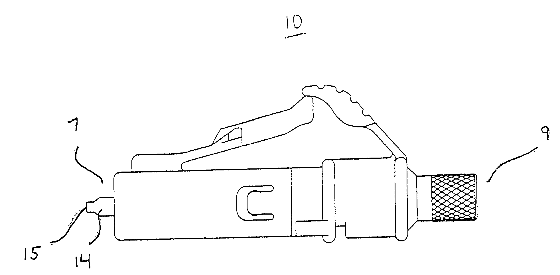
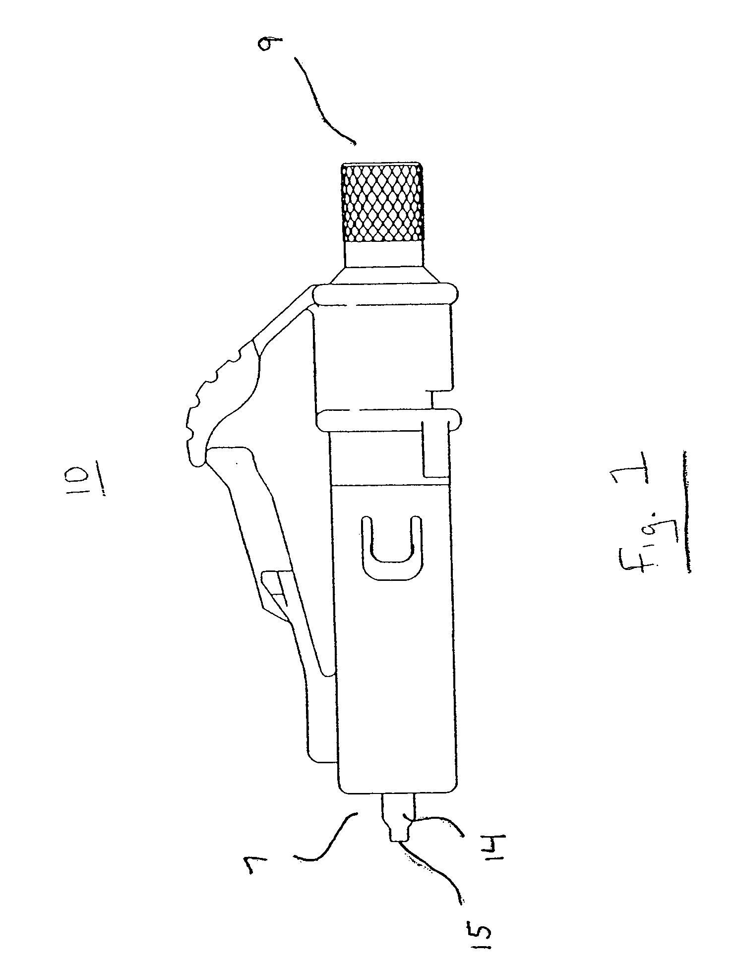
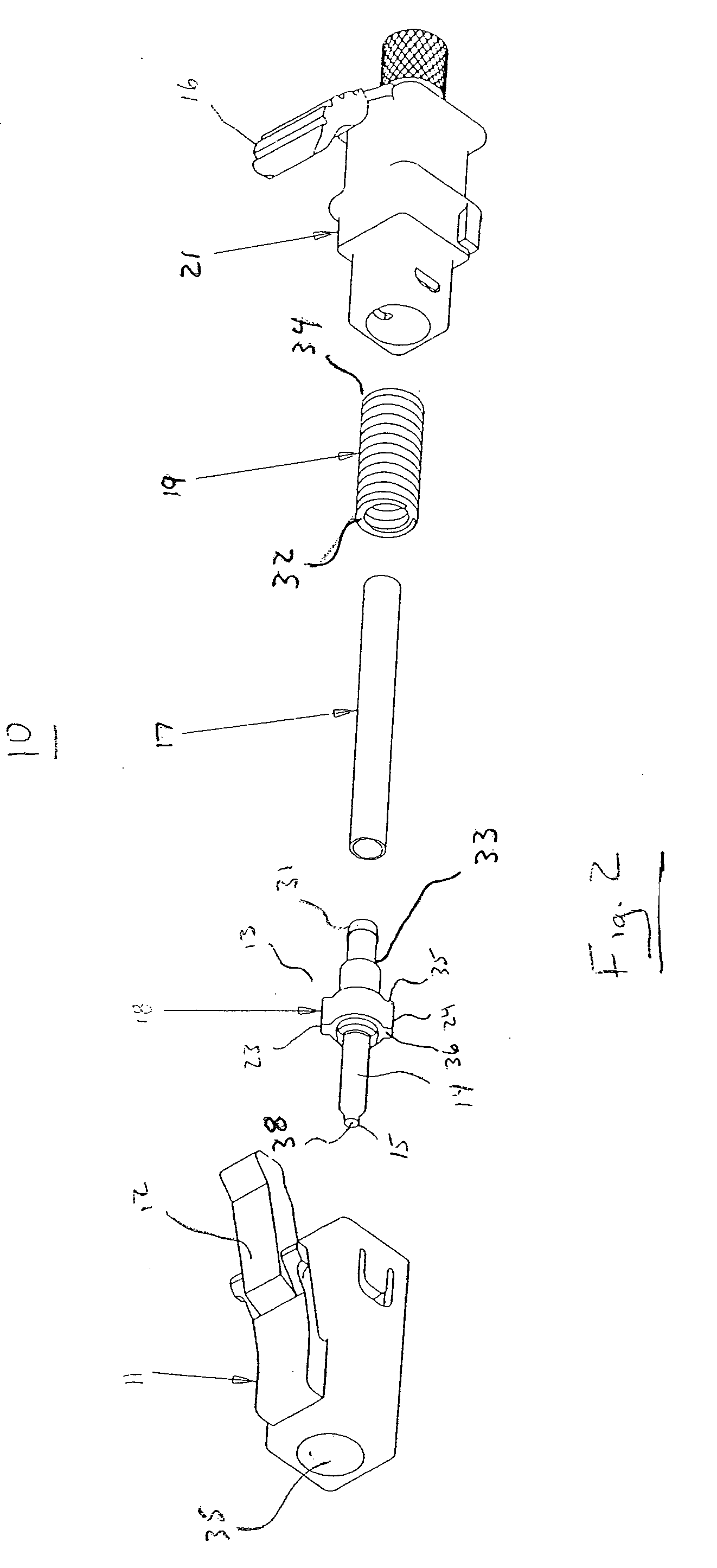
[0022] A preferred embodiment of the present invention is shown in FIGS. 1 through 6. The figures show an optical fiber connector assembly. The illustrated connector is an LC type connector, although the invention is not limited to this connector type and may be practiced with other connector types such as the SC-, FC-, and MU- connectors.

[0023] FIG. 1 shows a connector assembly 10 in accordance with the present invention in the assembled configuration. The connector assembly 10 has a front end 7 and a rear end 9. The present invention shall be discussed with reference to a single connector assembly 10; however, in use a pair of connector assemblies 10 would be joined by inserted the front end 7 of a first connector assembly 10 into an adapter where it would couple with the front end 7 of a second connector assembly 10. The front face 15 of a ferrule 14 contained within the first connector assembly would contact the front face 7 of a second connector assembly 10 to provide for conne...


PUM


Abstract

A method of assembling an optical fiber assembly comprising the steps of: (a) providing a ferrule sub-assembly comprising a ferrule having a front end and a fiber secured therein and a positioning member; (b) positioning the ferrule sub-assembly in a housing adapted to receive the positioning member in a plurality of predetermined radial positions; (c) preparing the front end such that the fiber is suitable for optical coupling with a mating device; (d) rotating the ferrule sub-assembly to at least a portion of the plurality of predetermined radial positions within the housing while measuring the power loss associated with each radial position to determine the optimal radial position; and (e) optionally polishing the end of the ferrule into the desired configuration after the optimum radial position is determined.

Description

REFERENCE TO RELATED APPLICATION[0001] This application claims priority to U.S. Provisional Application No. 60 / 401,901, filed Aug. 8, 2002, and hereby incorporated by reference.[0002] The present invention relates generally to an optical fiber connector, and, more specifically, to an optical fiber connector in which the ferrule position relative to the connector housing is adjustable.BACKGROUND OF INVENTION[0003] Optical fiber connectors are an essential part of substantially all optical fiber communication systems. For instance, such connectors are used to join segments of fiber into longer lengths, to connect fiber to active devices such as radiation sources, detectors and repeaters, and to connect fiber to passive devices such as switches and attenuators. The principal function of optical fiber connectors is to hold an optical fiber such that its core is axially aligned with the optical path of the device to which the connector is mating (e.g., another fiber). This way, the light...

Claims


Application Information

Patent Timeline
Patent Type & Authority Applications(United States)
IPC IPC(8): G02B6/38
CPCG02B6/3812G02B6/3871G02B6/3869G02B6/3843
Inventor ERDMAN, DAVID DONALDGURRERI, MICHAEL LAWRENCEMANNING, RANDY MARSHALL
Owner COMMSCOPE TECH LLC
Why Eureka
Try Eureka