

Ink jet printing apparatus and ink jet printing method
a printing apparatus and ink jet technology, applied in the direction of printing, electrical apparatus, pictoral communication, etc., can solve the problems of affecting the image quality of the dots to be printed by the nozzle, the inability to print on a print medium, and the inability to meet the requirements of printing mediums,
- Summary
- Abstract
- Description
- Claims
- Application Information
AI Technical Summary
Benefits of technology
Problems solved by technology
Method used
Image

Examples
first embodiment
[0127] Next, some examples of printing performed by using the ink jet printing apparatus and the printing method according to the invention will be explained.
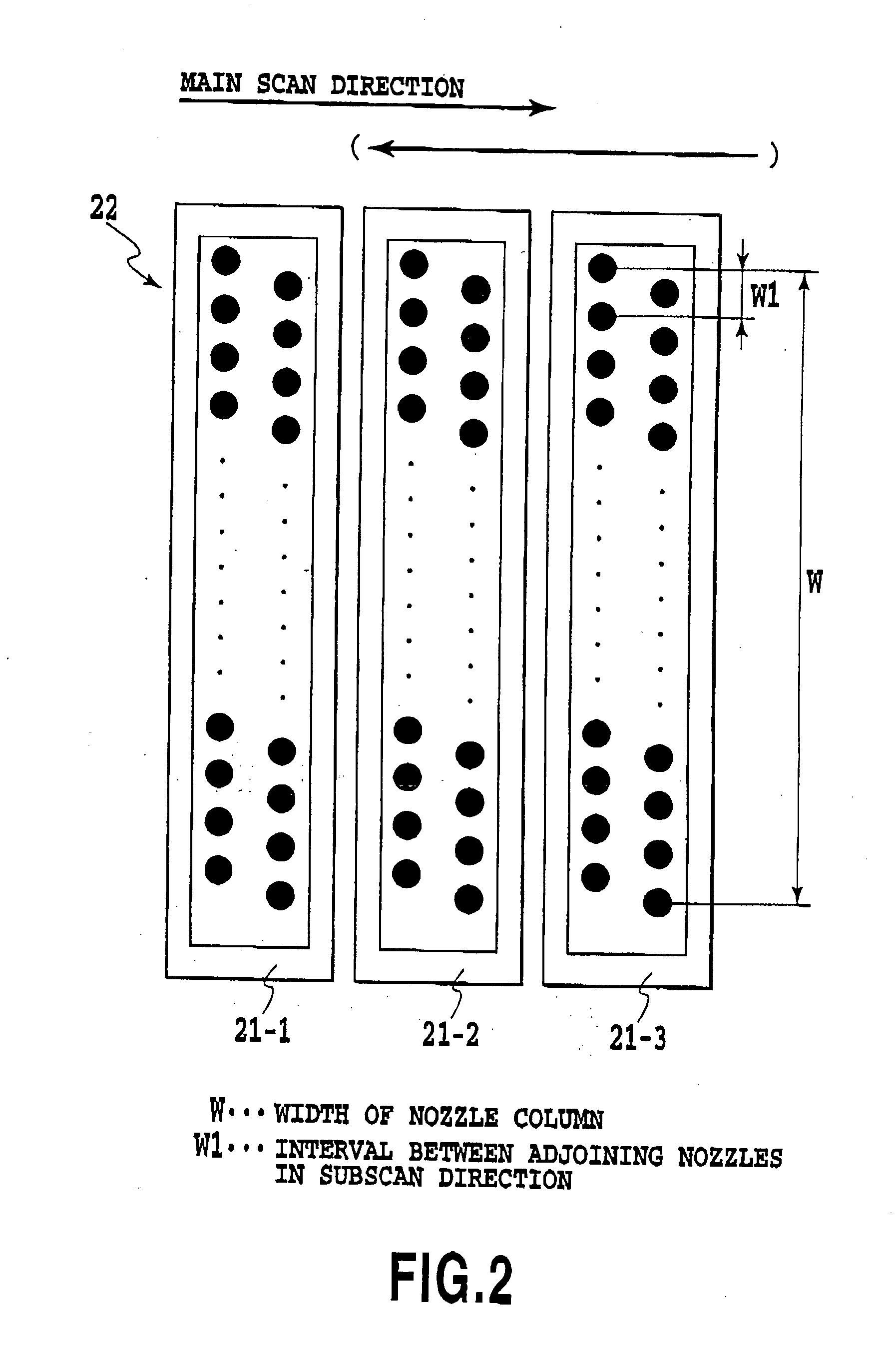
[0128] A print head used has a resolution of 1,200 dpi and an array of 4,096 nozzles, with an ink ejection volume (volume of each ink droplet) set to 4.5.+-.0.5 pl.
[0129] Inks containing colorants have the following compositions.
1 (Prescription: Y ink) Glycerine 5.0 parts by weight Thiodiglycol 5.0 parts by weight Urea 5.0 parts by weight Isopropyl alcohol 4.0 parts by weight Dystuff, C.I. Direct Yellow 142 2.0 parts by weight Water 79.0 parts by weight (Prescription: M ink) Glycerine 5.0 parts by weight Thiodiglycol 5.0 parts by weight Urea 5.0 parts by weight Isopropyl alcohol 4.0 parts by weight Dystuff, C.I. Acid Red 289 2.5 parts by weight Water 78.5 parts by weight (Prescription: C ink) Glycerine 5.0 parts by weight Thiodiglycol 5.0 parts by weight Urea 5.0 parts by weight Isopropyl alcohol 4.0 parts by weight Dystuff, C....
fifth embodiment
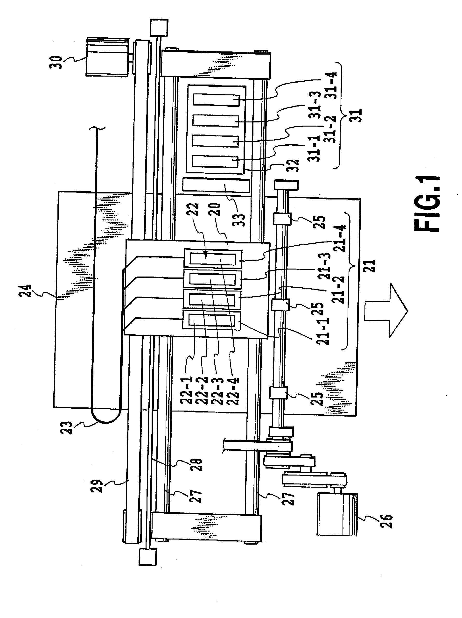
[0135] Next, the present invention will be explained. In this embodiment, too, the construction shown in FIG. 1 to FIG. 3 is used as in the preceding embodiment.
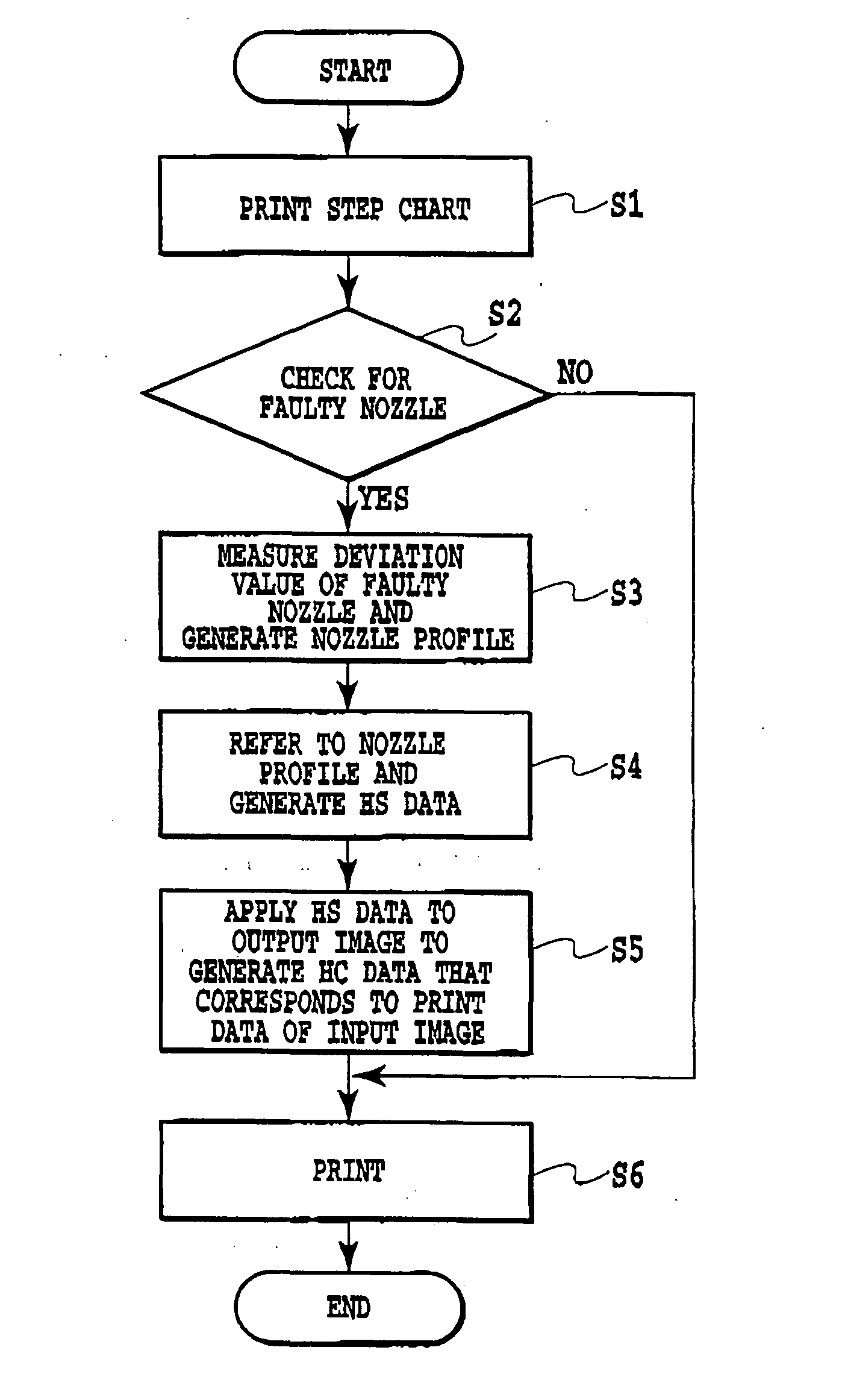
[0136] A generation of print head nozzle information, one of features of this embodiment, a generation of print information for each nozzle based on the nozzle information, and an actual printing operation will be explained by referring mainly to FIG. 15 and FIG. 16.
[0137] To generate the print information the following process needs to be taken. First, a check is made to see if there is any among the print head nozzles that projects ink droplets with deviations from an ideal print matrix. If there is such a nozzle, nozzle information needs to be determined which includes an amount of deviation of an ink droplet ejected from that nozzle with respect to the print matrix and, if necessary, a size and shape of an ink dot formed by the nozzle.
[0138] To obtain the nozzle information, a first step to be taken is to print a step pa...
example 2
[0165] Next, Example 2 of a printing operation performed by the ink jet printing apparatus and the printing method of the fifth embodiment of this invention will be described in the following.
[0166] A print head, as in the previous Example 1, has 4,096 nozzles arranged at a resolution of 1,200 dpi, with a single ink ejection volume (volume of an ink droplet) set to 4.5.+-.0.5 pl. Compositions of inks containing colorants are the same as those in Example 1.
[0167] A printing operation control was performed according to a sequence shown in the flow chart of FIG. 16.
[0168] First, a step chart of FIG. 4 was output and the printed step chart was measured by an optical sensor (scanner) not shown at a resolution of 4,800 dpi. Individual line segments of the step chart were subjected to line-thinning processing to determine gravity centers of ink dots and thereby measure Y deviation values of ink dots from ideal dot landing positions. At the same time, a solid printed chart was also read to ...
PUM
 Abstract
Description
Claims
Application Information