Optical scan apparatus and image formation apparatus

Inactive Publication Date: 2008-11-20
RICOH KK
View PDF34 Cites 26 Cited by
  • Summary
  • Abstract
  • Description
  • Claims
  • Application Information

AI Technical Summary

Benefits of technology

[0009]In view of solving the above problems, an object of the present invention is to provide an optical s

Problems solved by technology

However, there is a problem that along with the increase of the rotation speed of the polygon mirror, noise and vibration from a drive system is increased as well as power consumption, resulting in lowering durability of the apparatus.
Further, the speeding-up of the image outputs has a trade-off relation with formation of the high-density images so that image quality deteriorates as the rota

Method used


Image

  • Optical scan apparatus and image formation apparatus
  • Optical scan apparatus and image formation apparatus
  • Optical scan apparatus and image formation apparatus

Examples


first embodiment

[0024]Hereinafter, the embodiments of the present invention will be described with reference to the accompanying drawings.

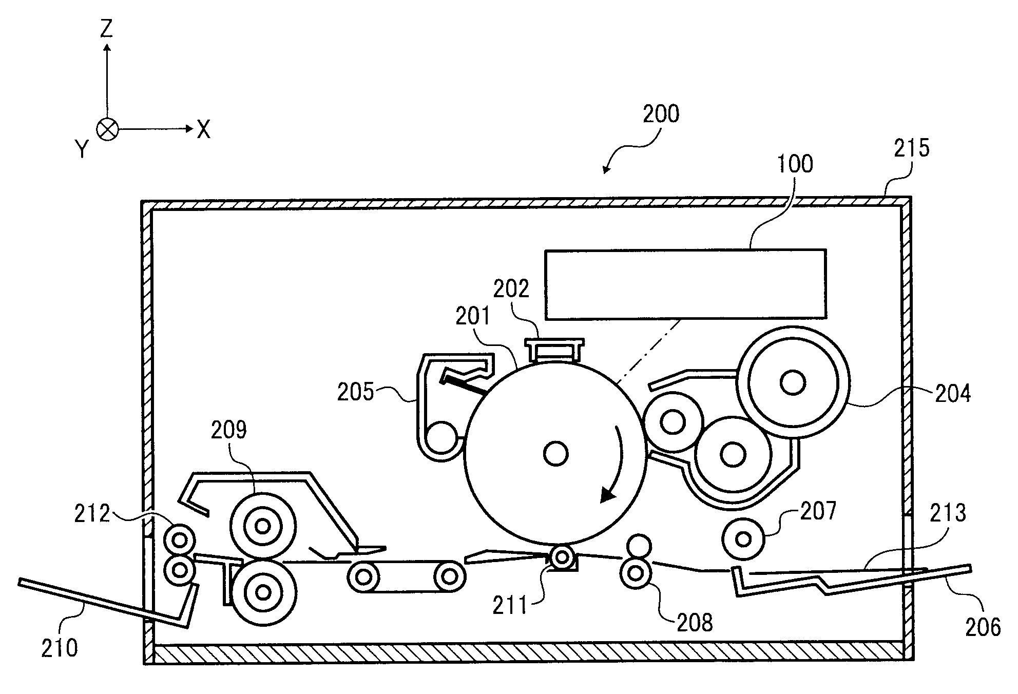
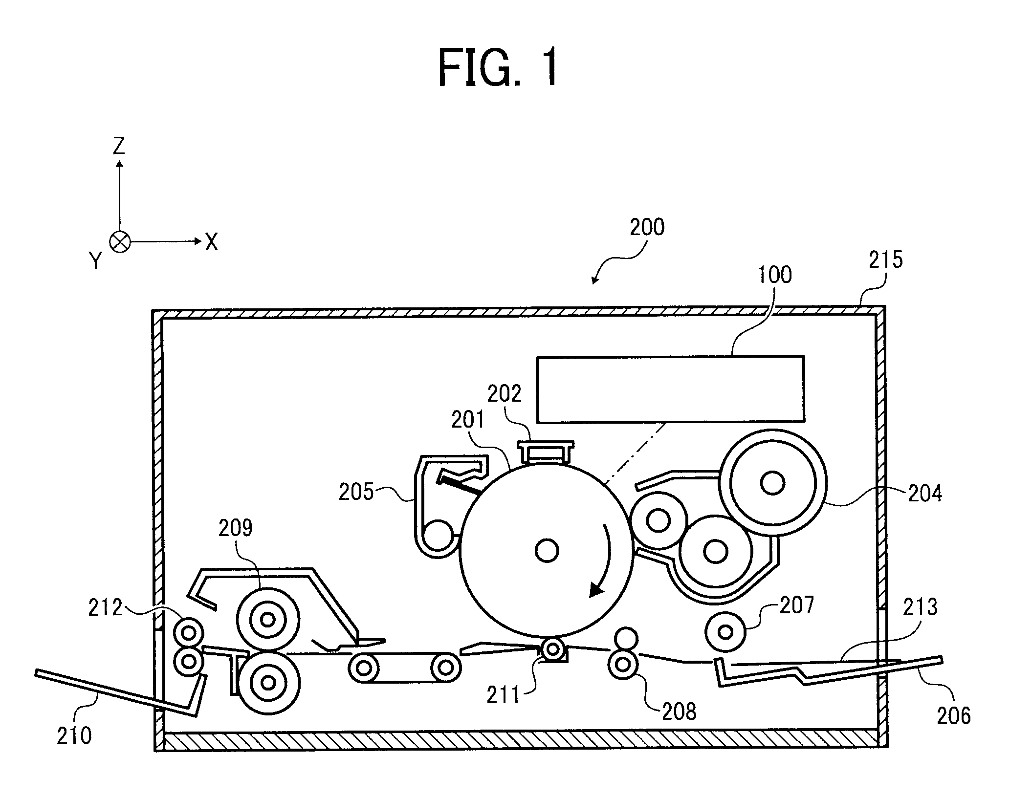
[0025]The first embodiment of the present invention will be described with reference to FIGS. 1 to 3. FIG. 1 shows the schematic structure of an image formation apparatus 200 according to the first embodiment.

[0026]The image formation apparatus 200 is a printer using a Carlson process and prints images by transferring toner images onto a sheet of paper. The image formation apparatus 200 includes, as shown in FIG. 1, an optical scan apparatus 100, a photoconductive drum 201, an electric charger 202, a toner cartridge 204, a cleaning case 205, a paper feed tray 206, a paper feed roller 207, a resist roller pair 208, a transfer charger 211, a fuse roller 209, a discharge roller 212, a paper discharge tray 210, a not-shown main controller for controlling the above components collectively, and a housing 215 containing the above components.

[0027]The housing 215 of a su...

second embodiment

[0068]Next, an image formation apparatus according to the second embodiment of the present invention will be described with reference to FIGS. 7 to 11. The identical or equivalent components thereof to those of the image formation apparatus according to the first embodiment will be given the same numeric codes, and description thereon will be omitted or simplified.

[0069]FIG. 7 shows a light source 10′ of the image formation apparatus according to the second embodiment. The light source 10′ is a surface emitting semiconductor laser array on which luminous points such as VCSELs are two-dimensionally arranged. It differs from the light source 10 of the first embodiment in the arrangement of luminous points. As shown in FIG. 7, 40 VCSELs are arranged in matrix of 5 rows, 8 columns on a light emitting plane (x-axis direction side in the drawing) of the light source 10′. The rows are arranged in a direction in parallel with the straight line L2 which makes an angle θ2 with the y-axis dire...


PUM


Abstract

An optical scan apparatus which deflects a plurality of light beams to scan a write region on a scan surface in a main scan direction is configured to include a light source which has a plurality of emission portions emitting the plurality of light beams arranged two-dimensionally on a plane in parallel to the main scan direction and a sub scan direction perpendicular to the main scan direction; a deflector which deflects the plurality of light beams from the plurality of emission portions; a light receiving element which receives the light beams and outputs a synchronous detection signal in accordance with the received light beams; and a control unit which selectively controls any one of the emission portions to emit a light beam upon each scanning and allows the light beam from the selected emission portion to be incident on the light receiving element via the deflector.

Description

CROSS-REFERENCE TO RELATED APPLICATIONS[0001]The present application is based on and claims priority from Japanese Patent Application No. 2007-128103, filed on May 14, 2007, and No. 2008-9468, filed on Jan. 18, 2008, the disclosure of which is hereby incorporated by reference in its entirety.BACKGROUND OF THE INVENTION[0002]1. Field of the Invention[0003]The present invention relates to an optical scan apparatus and an image formation apparatus, particularly to an optical scan apparatus which scans a surface with a plurality of light beams as well as to an image formation apparatus including the optical scan apparatus.[0004]2. Description of the Related Art[0005]A known image formation apparatus using the Carlson process forms images by, for example, scanning the surface of a rotating photoconductive drum with a plurality of light beams to form an electrostatic latent image thereon, visualizing the electrostatic latent image as a toner image, and fusing the toner image on a sheet of...

Claims


Application Information

Patent Timeline
IPC IPC(8): B41J2/455G02B26/08
CPCB41J2/473G02B26/123G02B26/127G06K15/1219G06K15/1261
Inventor SUZUKI, SEIZOMIFUNE, HIRONOBUHAYASHI, YOSHINORINIHEI, YASUHIRO
Owner RICOH KK
Why Eureka
Try Eureka