Rotation detecting device and wheel support bearing assembly utilizing the same

a technology of rotating detecting and bearings, which is applied in the field of rotating detecting, can solve the problems of inability to detect the movement of the magnet the gap between the magnets and the magnetic ring assembly would increase undesiredly, and the electric power output generated by the electric power generator would be reduced. , the effect of reducing the size of the electric power generator

Inactive Publication Date: 2004-06-03
NTN CORP
View PDF3 Cites 51 Cited by
  • Summary
  • Abstract
  • Description
  • Claims
  • Application Information

AI Technical Summary

Problems solved by technology

Also, where the magnetic ring assembly is also susceptible to saline dirt and grits, the anti-rusting treatment has to be applied to the magnetic ring assembly.
Accordingly, if the anti-rusting treatment is applied to the magnets and the magnetic ring assembly, particularly to respective surfaces of the magnetic ring assembly and the magnets that confront with each other, a gap between the magnets and the magnetic ring assembly would undesirably increase enough to lower the electric power output generated by the electric power generator.
Although the problem associated with reduction in electric power output of the electric power generator would be resolved if the number of turns of the coil accommodated in the magnetic ring assembly is increased and / or the magnets of a relatively large thickness are employed, any of those measures would result in an undesirable increase of the size of the electric power generator.
Also, if foreign matter enter between the respective surfaces of the magnetic ring assembly and the magnets that confront with each other, those surfaces would be scratched or otherwise damaged in contact with the foreign matter and the anti-rusting film or mold would then be impaired enough to allow rusting to occur in those surfaces.
However, with the above discussed conventional rolling bearing assembly of the type equipped with the electric power generator, the electric circuit unit 77 including the electric power source circuit, the processing circuit for processing the rotational speed detection signal, the transmission circuit and others is necessarily disposed at a location distant and separate from the electric power generator 76, hence involving a problem associated with complication in structure.
However, since the pulser ring and the sensing portion are exposed to the outside, a problem would often occur in that reduction in size of the wheel support bearing assembly tends to be hampered.
For this reason, the mounting members 89 and 90 have to be precisely machined, resulting in increase of the cost.
However, in the wheel support bearing assembly of the structure shown in and discussed with reference to FIG. 39, the sealing member 91 is interposed between the mounting members 89 and 90 and, therefore, no contact pressure would be secured in the sealing member 91 due to an error in positioning of the mounting members 89 and 90 relative to each other, resulting in a risk of incomplete sealing.
Yet, in view of the presence of the peripheral component parts, the sectional surface area of the electric power generator 86 cannot be increased and, therefore, it is generally difficult to secure the electric power that can be generated.
Where the wireless transmission device 87 is employed, the space for installation thereof is additionally limited.
Considering that the wheel support bearing assembly is used under a severe environment such as exposed to a ground surface and, accordingly, if a wiring is employed for outputting the rotational speed detection signal from the rotation detecting device and also for connection with the electric power source, a problem often occurs which is associated with breakage of the wiring.
On the other hand, the divided structure often constitutes a cause of increase of a magnetic resistance in a joint between the divided ring members.
However, since the divided ring members are so designed as to be combined together with the respective portions in section along the axial direction being capped one over the other, so that the connecting strength with which the respective portions of the divided ring members can be connected with each other can increase as the magnetic ring assembly undergoes deformation upon press-fitting thereof on the inner or outer member, the magnetic resistance in the magnetic circuit defined in the magnetic ring assembly does not increase, permitting the electric power generated to be secured satisfactorily.

Method used


Image

  • Rotation detecting device and wheel support bearing assembly utilizing the same
  • Rotation detecting device and wheel support bearing assembly utilizing the same
  • Rotation detecting device and wheel support bearing assembly utilizing the same

Examples


first embodiment

[0135] FIG. 5 illustrates a modified form of the seal contact area according to a second preferred embodiment of the present invention. In this modification, a core metal 39 of the multi-pole magnet assembly 13 is formed integrally with the slinger 23 that is made of stainless steel. This slinger 23 includes a first hollow cylindrical wall of a reduced diameter that defines the core metal 39, a second hollow cylindrical wall 41 of a large diameter, an intermediate annular shoulder 40 intervening between the first and second hollow cylindrical walls 39 and 41, and an inclined collar 42 continued axially outwardly from the second hollow cylindrical wall 41 with a free end of the inclined collar 42 bent to extend upright in a radially outward direction. This slinger 23 is mounted on the inner member 3, particularly the inner race forming member 3b with the second hollow cylindrical wall 41 thereof press-fitted onto a shoulder 43 of the cup portion 37 of the constant velocity universal ...

fifth embodiment

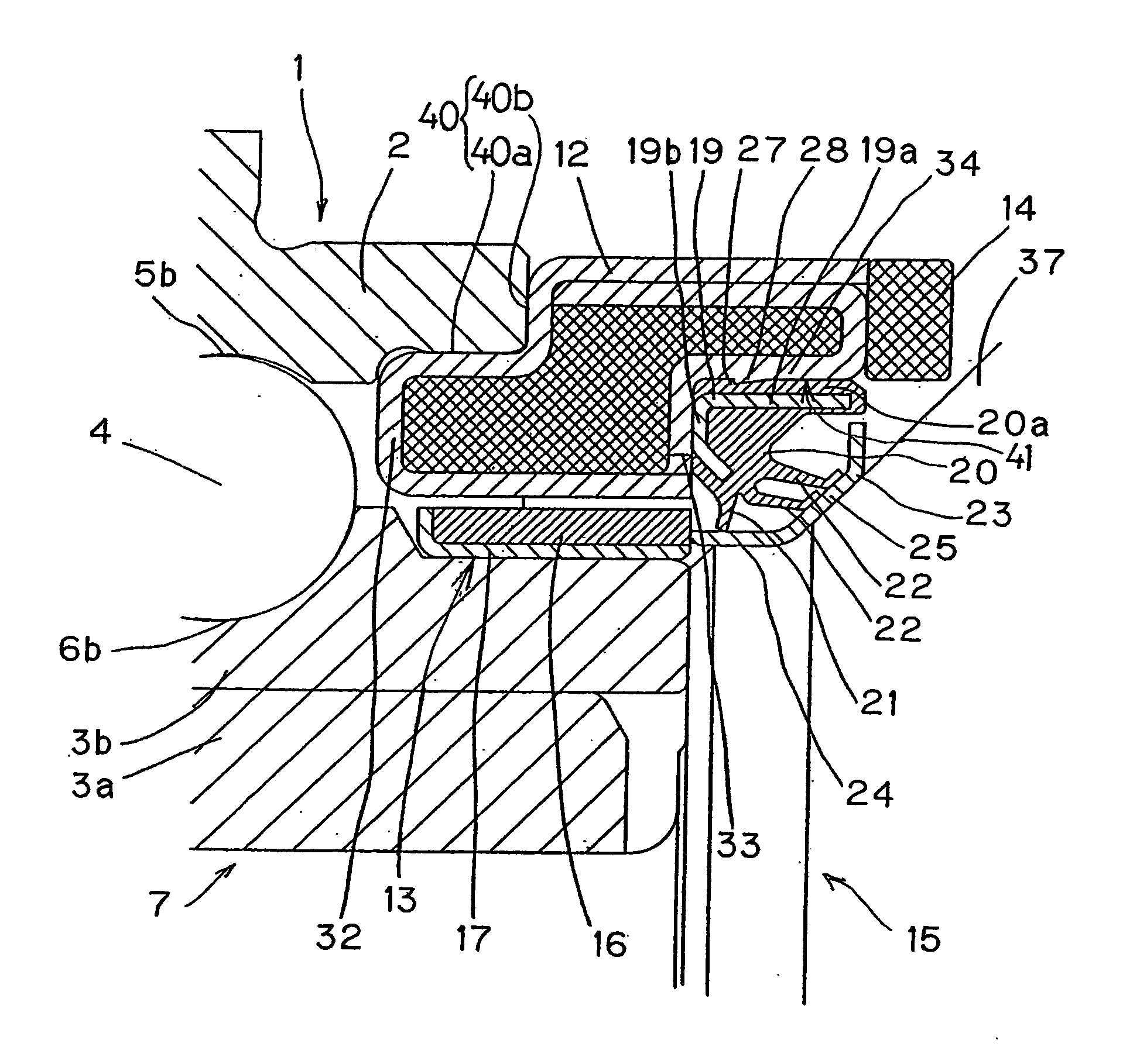
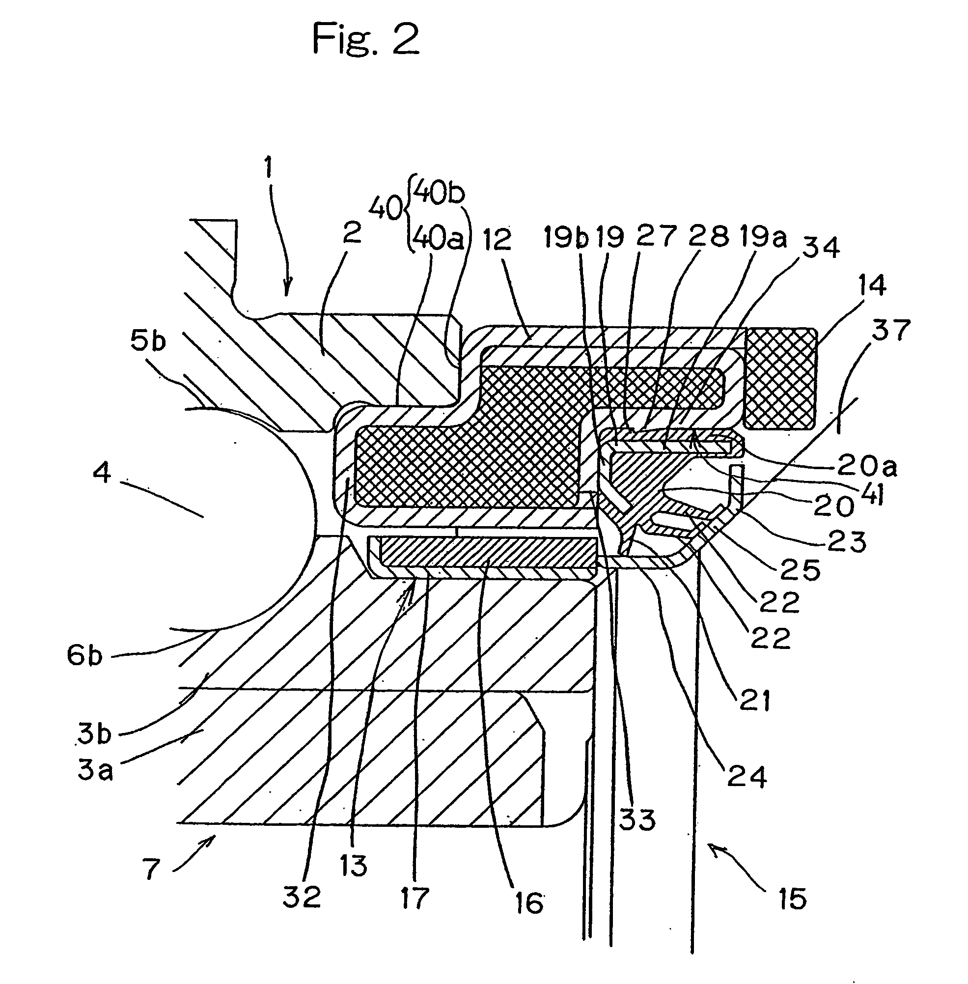
[0144] In the fifth embodiment shown in FIG. 8, the magnetic ring assembly 12 has an outer peripheral surface of a generally cylindrical configuration including a reduced diameter portion and a large diameter portion with an annular step intervening therebetween. This magnetic ring assembly 12 is carried by the outer member 2 with the reduced diameter portion thereof press-fitted into the inner peripheral surface of the outer member 2. In other words, the magnetic ring assembly 12 has an axial end portion press-fitted into the inner periphery of the outer member 2. The inner peripheral surface and the annular side wall 33 of the magnetic ring assembly 12 represent a flat surface with no step formed therein.

[0145] The mounting ring 26 for the wireless transmission device 14 is integrated together with the magnetic ring assembly 12 by allowing the mounting ring 26 to be firmly sandwiched between the respective outermost peripheral portions 35 and 36 of the first and second ferromagnet...

sixth embodiment

[0147] In the sixth embodiment shown in FIG. 9, the wireless transmission device 14 is mounted on the outer member 2 by mounting the outer cylindrical body 26c of the mounting ring 26 on the outer peripheral surface of the outer member 2. In this structure, material for the mounting ring 26 does not need to be magnetic provided that it has a rust proof. For example, austenite stainless steel such as identified by SUS 304 according to the Japanese Industrial Standard (JIS) may be employed therefor. However, the magnetic ring assembly 12 may be made of a material having no rust proof, but having a high magnetic permeability. By way of example, Permalloy.RTM., silicon steel plate, rolled steel plate or the like may be employed as material for the magnetic ring assembly 12. The use of the material of a high magnetic permeability is effective to increase the efficiency of electric power generation and also to reduce the size of the electric power generator 11.


PUM


Abstract

To provide a rotation detecting device with a function of transmitting a rotational speed detection signal wireless and enable the rotation detecting device to be assembled compact in size without requiring any anti-rusting treatment to a multi-pole magnet assembly and a magnetic ring assembly, the rotation detecting device includes an electric power generator (11) for generating an electric power by a relative rotation between a non-rotatable member (1) and a rotatable member (7). The electric power generator (11) includes a multi-pole magnet assembly (13) and a magnetic ring assembly (12). A wireless transmission device (14) for transmitting the rotational speed detection signal outputted by the electric power generator (11) is employed. A sealing member (18) is also employed for sealing a working space delimited between the non-rotatable member (1) and the rotatable member (7), and the multi-pole magnet assembly (13) and the magnetic ring assembly (12) of the electric power generator (11) confront with each other at a location inwardly of the sealing member (18). The sealing member (18) is mounted on the magnetic ring assembly (12) or the wireless transmission device (14) of an annular configuration.

Description

[0001] 1. Field of the Invention[0002] The present invention relates to a rotation detecting device for detecting the number of revolutions of a rotating element such as a wheel and for transmitting wireless an electric signal indicative of the detected number of revolutions. The present invention also relates to a wheel support bearing assembly utilizing the rotation detecting device referred to above and to a rolling bearing assembly equipped with an electric power generator that provides an electric power source or the like for the rotation detecting device of the type referred to above. The rolling bearing assembly equipped with the electric power generator can find a variety of applications such as in a wheel support bearing assembly provided with a wireless sensor and an ABS system.[0003] 2. Description of the Prior Art[0004] A rotation detecting device for detecting the number of revolutions, or the rotational speed for short, that is equipped with an electric power generator...

Claims


Application Information

Patent Timeline
Patent Type & Authority Applications(United States)
IPC IPC(8): F16C33/78G01P3/44
CPCF16C19/186F16C33/78F16C33/7886F16C41/004F16C41/007F16C33/7876F16C2326/02G01P3/443G01P3/487H02K7/1846F16C41/008
Inventor MIZUTANI, MASATOSHITAJIMA, EIJIOHTSUKI, HISASHINORIMATSU, TAKAYUKIOKADA, KOICHITAKAHASHI, TORUOHBA, HIROAKIIKEI, KATSUYUKI
Owner NTN CORP
Why Eureka
Try Eureka