Optical interrogation system and sensor system

an interrogation system and optical technology, applied in the direction of converting sensor output, electromagnetic transmission, transmission, etc., can solve the problems of wavelength measurement system, wavelength measurement system, and the operating bandwidth of optical source and wavelength measurement system

Inactive Publication Date: 2004-06-17
MOOG INSENSYS
View PDF3 Cites 76 Cited by
  • Summary
  • Abstract
  • Description
  • Claims
  • Application Information

AI Technical Summary

Problems solved by technology

This is an inherent feature of a scanning instrument such as an optical spectrum analyser, but presents a problem for instruments like wave-meters.
Another disadvantage of WDM based systems is that as the number of gratings in the array increases so does the required operating bandwidth of the optical source and the wavelength measuring system.
The difficulty in operating this type of TDM based system is that it requires a wavelength measuring system that can operate at high speed.
The difficulty with this TDM technique is that it requires high-speed photodiodes to detect the reflected pulses and high-speed signal processing electronics.
The need to have a scanning optical source, such as a tuneable laser diode or a broadband light source and scanning filter, is also a problem since these devices are often bulky and expensive.
A problem faced by all of these grating interrogation systems is that it is difficult to obtain high-power broad bandwidth optical sources.
In a TDM based system, this problem is compounded by the fact that only short pulses with long inter-pulse delays are received at the measurement system, resulting in a further (often profound) reduction in the average optical power received by the measurement system.
Increasing grating reflectivity increases the available signal at the measurement system, but has the disadvantage of limiting the total number of gratings that can be present within the array.
This is because for every grating in the array that the incident pulse has to pass through, some of its power is lost as it is reflected back from the grating.
The more gratings the pulse passes through, the more power it loses.
In addition, the reflected light from a grating, which propagates back towards the measurement system, will also experience decay in power due to further reflections from other gratings between itself and the measurement system.
An additional disadvantage of using high reflectivity gratings within a TDM based sensor system is that significant interference can occur due to multiple reflections of the illuminating optical pulses.
The main problem with existing OTDR technology is that it requires very fast signal processing electronics in order to distinguish the arrival times of different reflected pulses.
The use of fast electronics means that the measurement accuracy of the magnitude of reflected pulses is low.
In addition, the reflected optical signals are generally of low optical power, resulting in poor signal-to-noise ratios.

Method used


Image

  • Optical interrogation system and sensor system
  • Optical interrogation system and sensor system
  • Optical interrogation system and sensor system

Examples


first embodiment

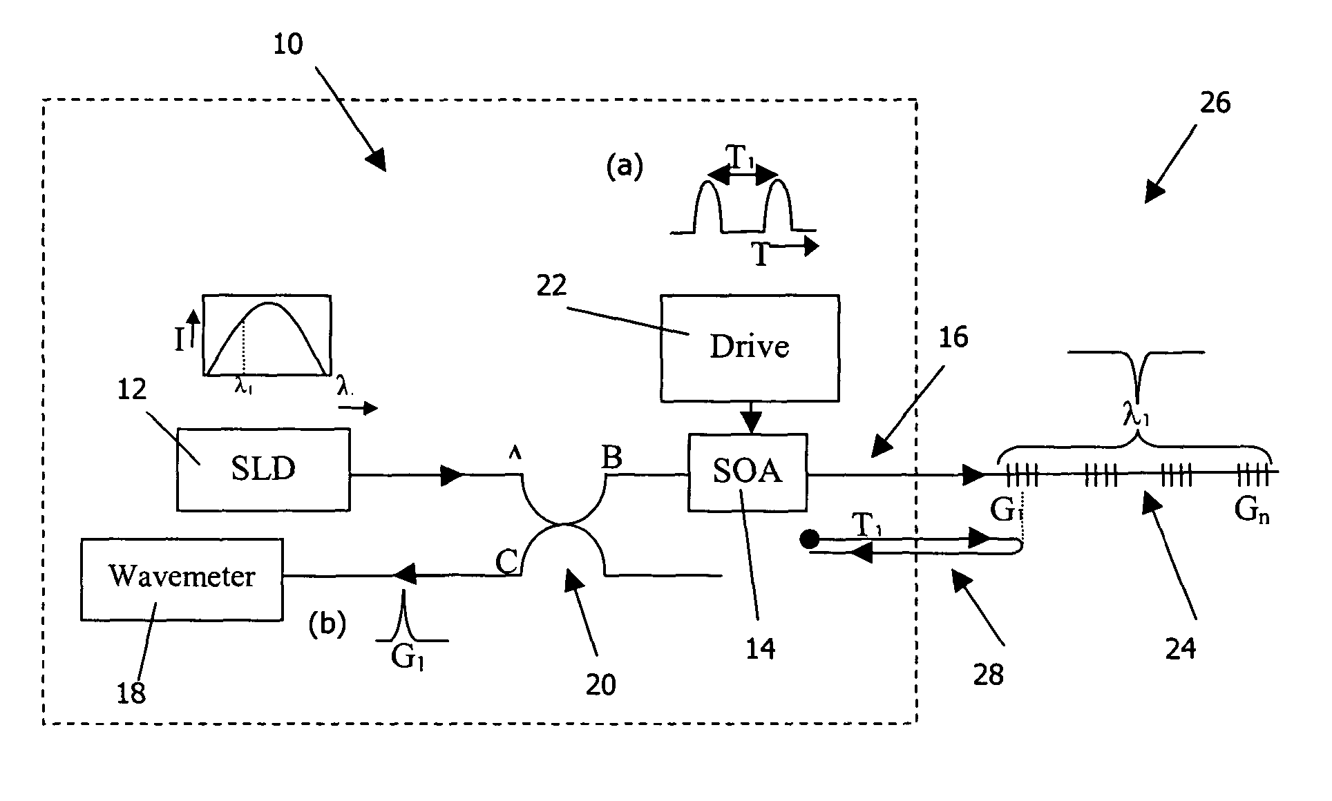
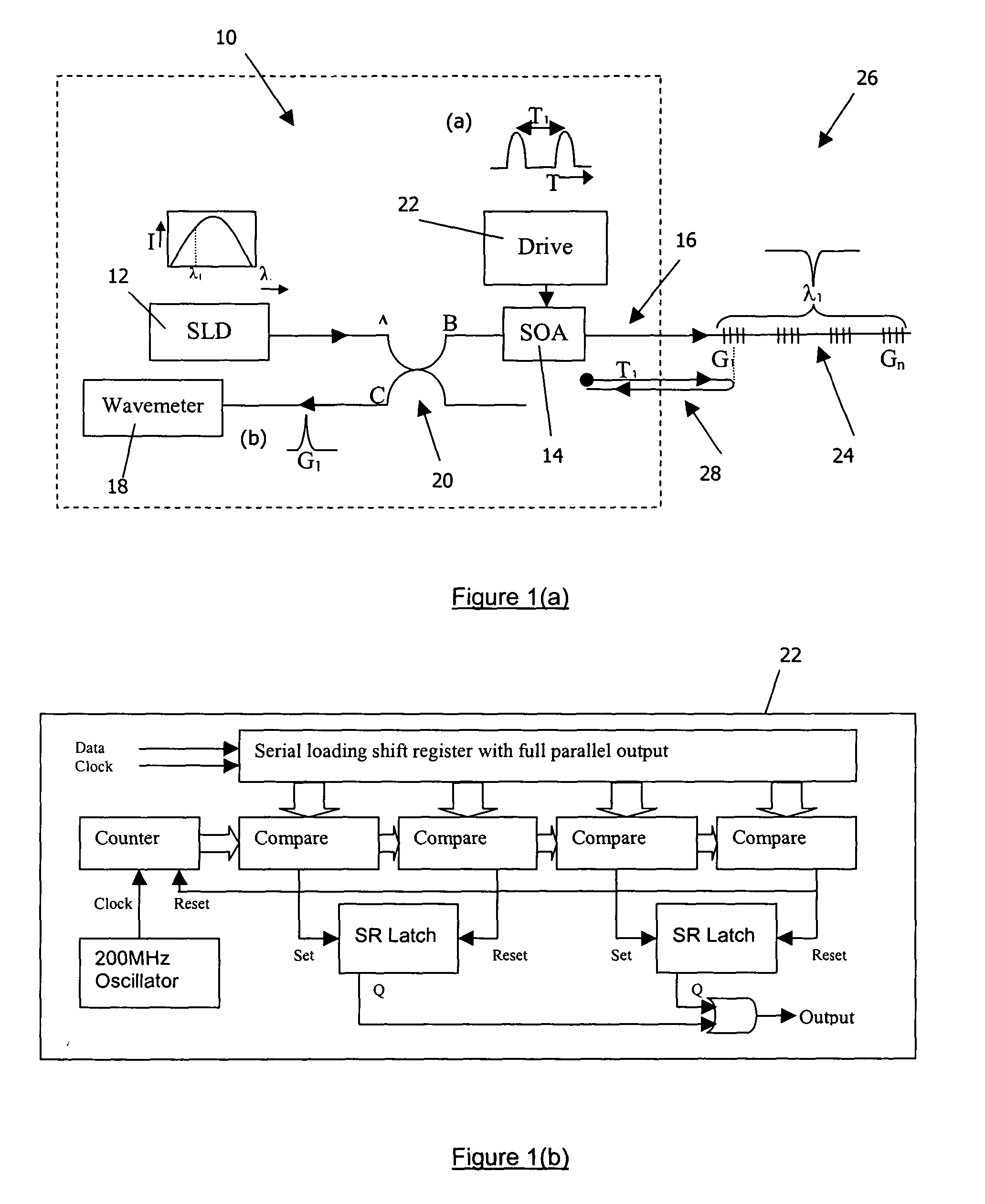
[0073] the invention provides an optical interrogation system 10, as shown in FIG. 1(a). The interrogation system 10 comprises an optical source 12, 14 operable to generate optical pulses, to be coupled into an optical waveguide 16 containing reflective optical elements, in this example gratings G, to be interrogated. The interrogation system 10 further comprises optical amplifying and gating means, which in this example takes the form of a bi-directionally operable semiconductor optical amplifier (SOA) 14. The SOA 14 is optically coupled to the waveguide 16 containing the gratings G to be interrogated. The interrogation system 10 also comprises optical detection means, which in this example takes the form of a wavemeter 18 optically coupled to the SOA 14. The wavemeter 18 is operable to evaluate the wavelength of a returned optical pulse transmitted by the SOA 14.

[0074] In this example, the optical source comprises a continuous wave (CW) optical source, in the form of a super-lumin...

second embodiment

[0081] To interrogate one or more reflective optical elements the interrogation system 10 is coupled to an optical waveguide containing one or more reflective optical elements to be interrogated. In this example, the interrogation system 10 is shown coupled to an optical fibre 16 including a sensing section 24 in which an array of fibre Bragg gratings (G.sub.1 to G.sub.n) are provided. The interrogation system 10 and the array of gratings together form an optical sensor system 26 according to the invention, each of the gratings G within the array forming a sensing element. The resonant wavelengths of each of the gratings G are substantially the same in this example, each grating G therefore operating within the same optical channel. In this example the gratings G are 2.5 mm in length and have a resonant wavelength of 1550 nm, a spectral bandwidth of 0.2 nm and a transmission loss of 4%. The four gratings shown in FIG. 1(a) are intended to illustrate an array of up to n gratings, whe...

fourth embodiment

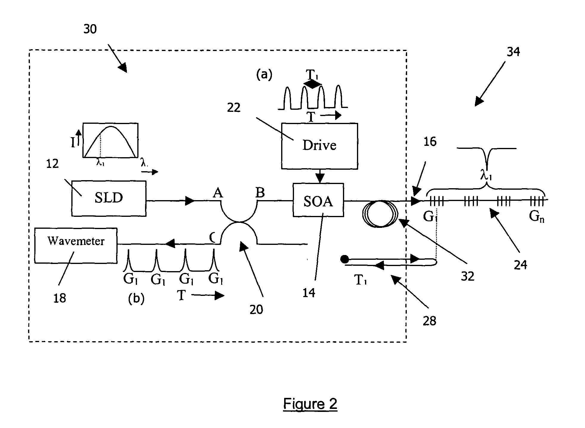
[0101] When the interrogation system 30 is coupled to the optical fibre 16 containing an array of gratings G to be interrogated, as described above, they together form an optical fibre grating sensor system 34 according to the invention.

[0102] FIG. 4 shows an optical interrogation system 40 according to a fifth embodiment of the invention. The interrogation system 40 of this embodiment is substantially the same as the interrogation system 30 according to the third embodiment, with the following modification. The same reference numerals are retained for corresponding features.


PUM

PropertyMeasurementUnit
velocityaaaaaaaaaa
reflectivityaaaaaaaaaa

Abstract

An optical interrogation system 10 includes optical amplifying and gating apparatus, in the form of a semiconductor optical amplifier (SOA) 14 and an optical source 12, 14. Drive apparatus 22 (an electrical pulse generator driven by a variable frequency oscillator) is provided to generate electrical drive pulses (see inset (a)) which are applied to the SOA 14, to cause the SOA 14 to switch on and off. The optical source comprises a super-luminescent diode (SLD) 12, the CW output from which is gated into optical pulses by the SOA 14. The SOA 14 is optically coupled to the waveguide 16 containing an array of reflective optical elements (gratings G) to be interrogated. The interrogation system further includes an optical detector 18, optically coupled to the SOA 14, operable to evaluate the wavelength of a returned optical pulse transmitted by the SOA 14.

Description

[0001] The invention relates to an optical interrogation system and to an optical sensor system incorporating the optical interrogation system.DESCRIPTION OF THE RELATED ART[0002] The two most widely used methods of interrogating gratings within a multi-grating array are wavelength division multiplexing (WDM) and time division multiplexing (TDM). In the case of WDM based systems, each grating within the array is fabricated to have a different resonant wavelength, located within a different wavelength window. A continuous wave broad bandwidth optical source is used to illuminate all of the gratings simultaneously, and the resulting reflected signal from each grating is simultaneously present in the output spectrum presented to a wavelength measuring system. The wavelength measuring system must therefore be able to measure multiple wavelengths simultaneously. This is an inherent feature of a scanning instrument such as an optical spectrum analyser, but presents a problem for instrumen...

Claims


Application Information

Patent Timeline
Patent Type & Authority Applications(United States)
IPC IPC(8): G01D5/353G01K11/32H04B10/071
CPCG01D5/35383H04B10/071G01K11/3206
Inventor EVERALL, LORNA ANNELLOYD, GLYNN DAVID
Owner MOOG INSENSYS
Why Eureka
Try Eureka