
Optical polarizing films with designed color shifts

Inactive Publication Date: 2004-07-01
3M INNOVATIVE PROPERTIES CO
View PDF18 Cites 31 Cited by
  • Summary
  • Abstract
  • Description
  • Claims
  • Application Information

AI Technical Summary

Benefits of technology

0009] The present application discloses films whose apparent color change with angle does not require the presence of a r

Problems solved by technology

However, the plurality of layers provide substantially no reflection bands for normally incident light.

Method used


Image

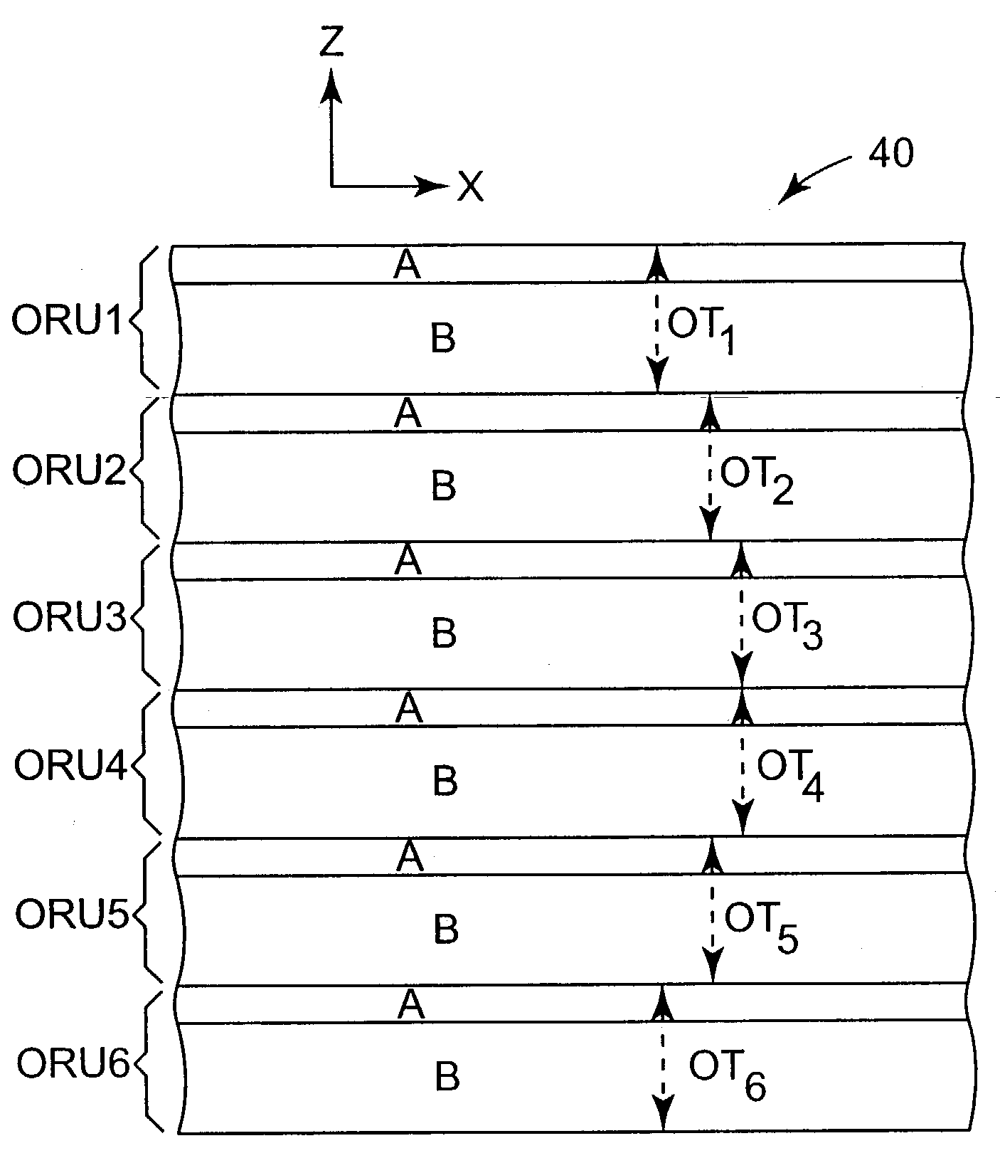
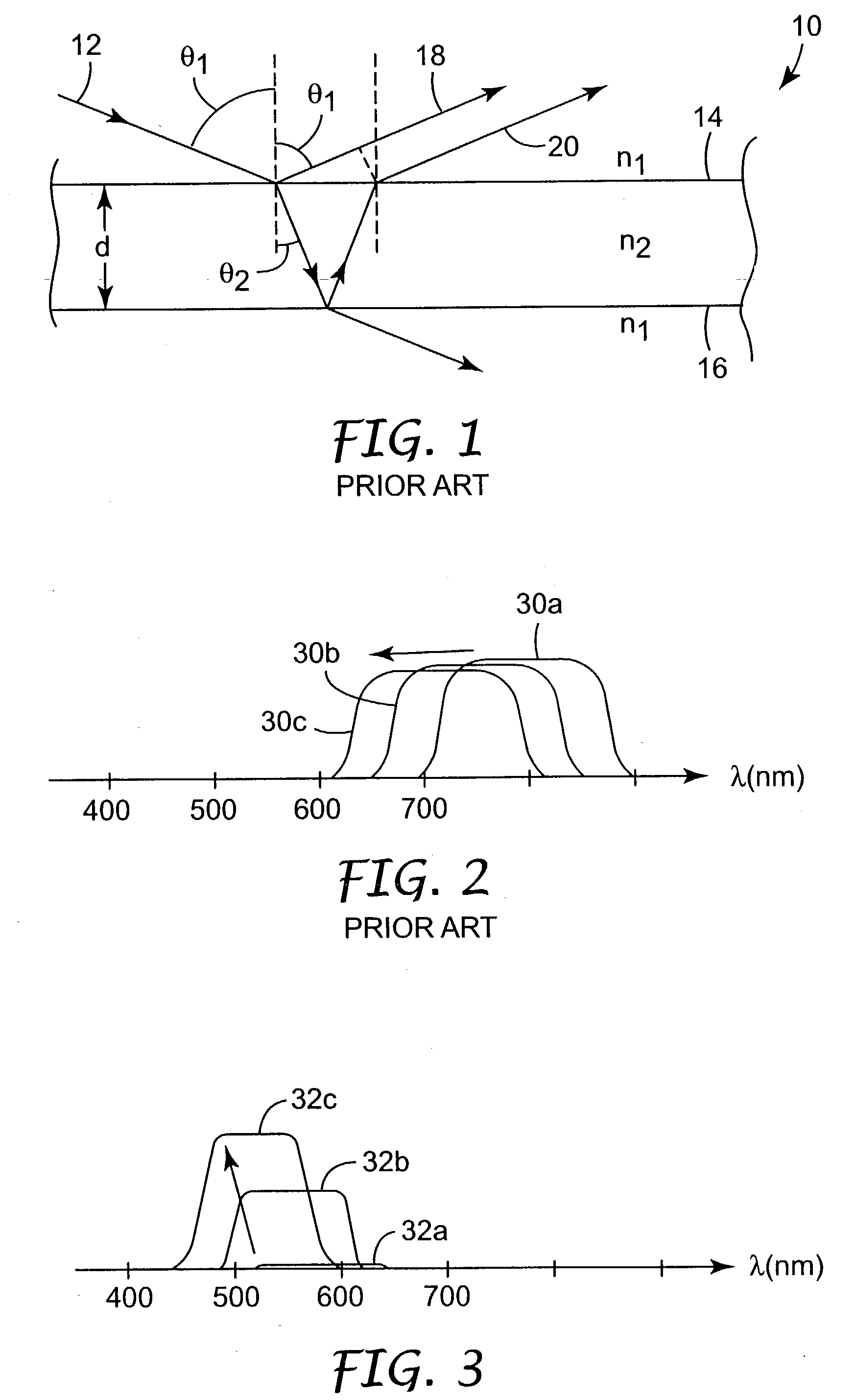
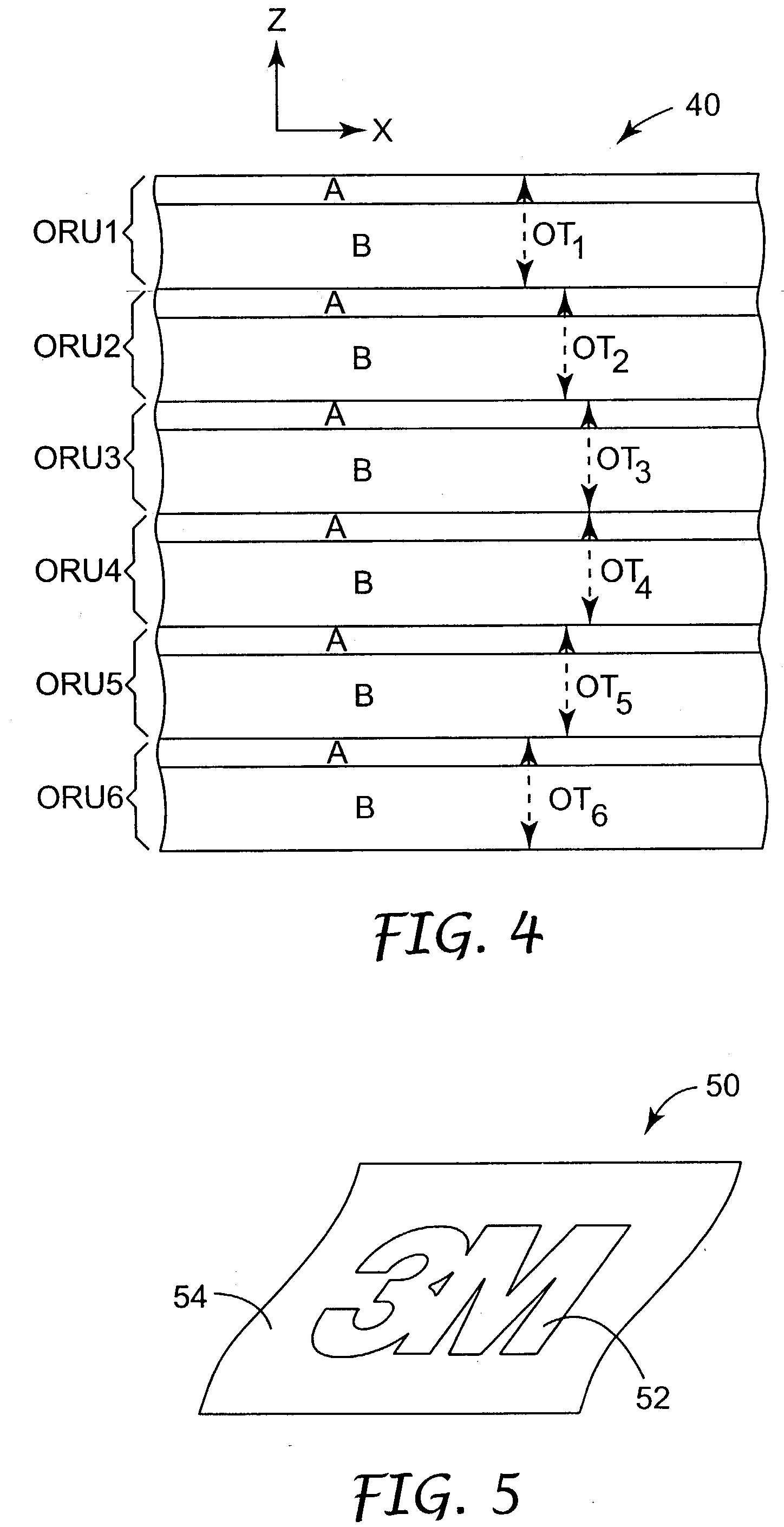
  • Optical polarizing films with designed color shifts
  • Optical polarizing films with designed color shifts
  • Optical polarizing films with designed color shifts

Examples


example

[0042] An example film will now be described. The polymer used in the isotropic layers of the film construction was specially formulated to achieve the necessary rheological, chemical, thermal, and optical properties. The polymers used in the film were chosen and / or developed according to the following conditions: they should be coextrudable; they should have adequate interlayer adhesion; and the isotropic polymer should have an unusually high refractive index in order to match the in-plane refractive indices of the birefringent polymer after stretching, and a low enough glass transition temperature so that it remains isotropic when oriented under conditions necessary to cause birefringence in the other polymer material. Preferably, the film is maintained at a temperature of at least about 20.degree. C. above the glass transition temperature of the isotropic material during stretching.

Polymer 1--co-PEN-HNLT

[0043] A copolyester was synthesized in a batch reactor with the following ra...


PUM

PropertyMeasurementUnit
Optical reflectivityaaaaaaaaaa
Thicknessaaaaaaaaaa
Angleaaaaaaaaaa

Abstract

Multilayer films are provided that exhibit a colored appearance when viewed at an oblique angle as a result of one or more reflection bands in the visible region of the spectrum. The films however provide no substantial reflection bands in either the visible or near infrared regions for light normally incident on the film. The films can be made to shift from clear at normal incidence to an arbitrary designed color at an oblique angle without necessarily becoming cyan.

Description

[0001] The present invention relates to optical films. More particularly, the present invention relates to optical films whose apparent color changes as a function of viewing geometry.[0002] Optical films that exhibit a visible color shift as a function of viewing geometry are known. See, e.g., PCT Publication WO 99 / 36258 (Weber et al.) entitled "Color Shifting Film". See also U.S. Pat. No. 6,045,894 (Jonza et al.) entitled "Clear to Colored Security Film". These references disclose many different films, each of which exhibits a shift in apparent color as the observation or incidence angle .theta. (measured from the surface normal) changes. Filters that comprise a glass or other rigid substrate having a stack of inorganic isotropic materials deposited thereon can also exhibit color shifts.[0003] A common feature of these films is the presence of one or more reflection bands for normally incident light (.theta.=0), which band(s) then shift to shorter wavelengths as .theta. increases....

Claims


Application Information

Patent Timeline
IPC IPC(8): B32B7/023G02B5/28
CPCB32B7/02B32B27/36B42D2035/24Y10T428/2495G02B5/305Y10T428/24942G02B5/287B42D25/45B42D25/355B32B7/023G02B5/28G02B5/30
Inventor HEBRINK, TIMOTHY J.GILBERT, LAURENCE R.JONZA, JAMES M.RUFF, ANDREW T.
Owner 3M INNOVATIVE PROPERTIES CO
Learn More