Work support

a technology of support rods and supports, applied in the direction of chucks, mechanical equipment, manufacturing tools, etc., can solve the problems of unstable advancing motion of rods and difficult spring force for rods to advan

Inactive Publication Date: 2004-07-08
PASCAL ENG
View PDF4 Cites 12 Cited by
  • Summary
  • Abstract
  • Description
  • Claims
  • Application Information

AI Technical Summary

Problems solved by technology

However, since the tip of the rod abuts against the work piece with a light force in order to prevent the rod tip abutment from causing any elastic deformation of the work piece, the weight of the hose or tube connected to the work support side may make it difficult for the rod to advance by the spring force.
The resistance can increase and the weight balance of the rod can deteriorate if the hose is surrounded by chips and debris from machining, so that the rod's advancing motion can become unstable.

Method used


Image

  • Work support
  • Work support
  • Work support

Examples


Embodiment Construction

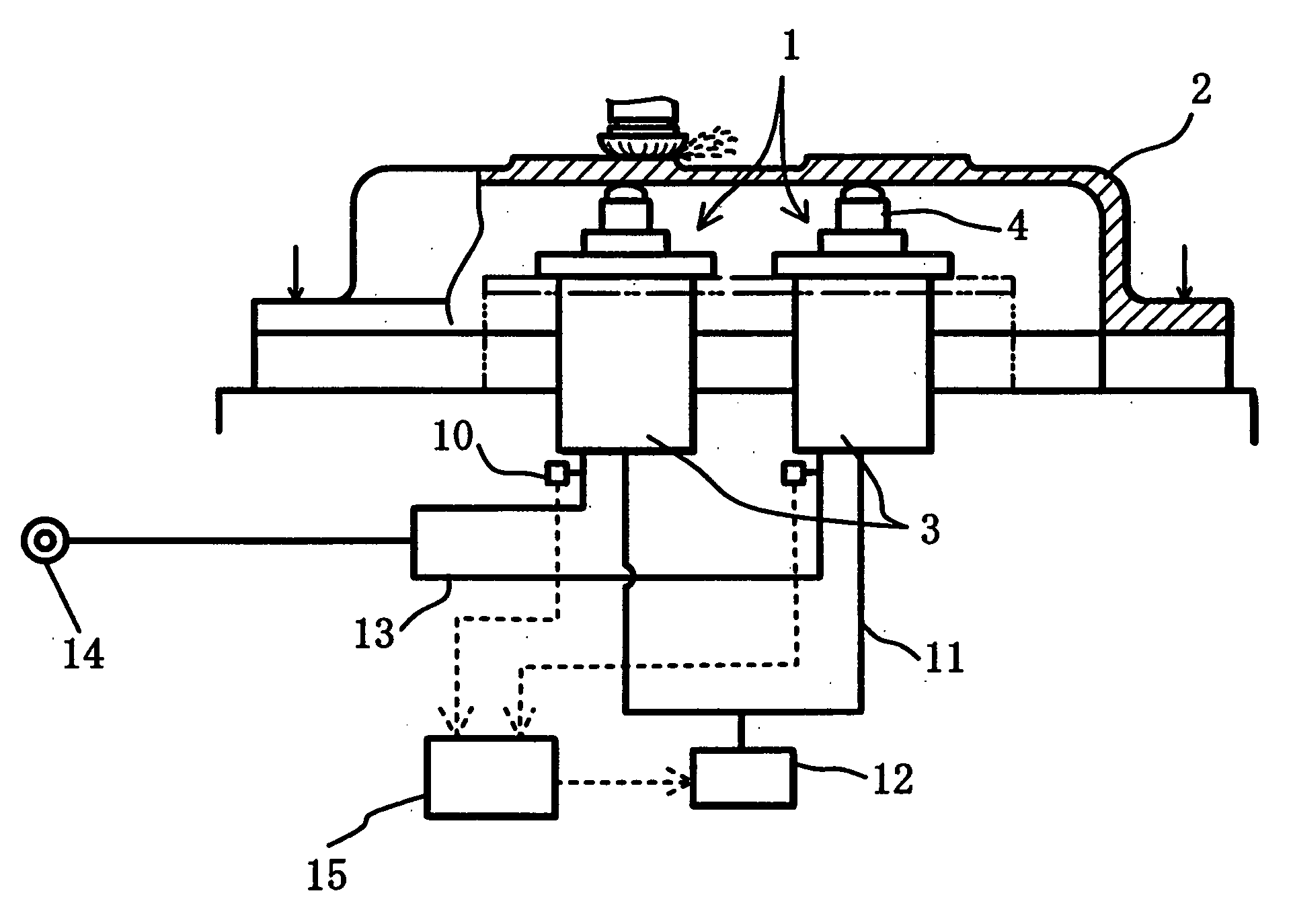
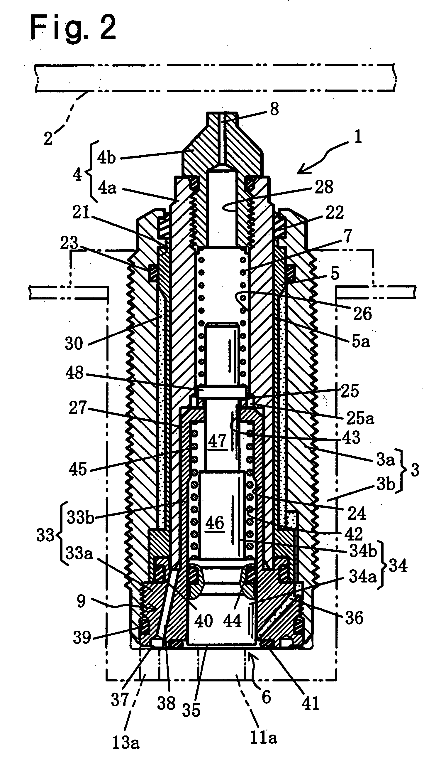
[0024] A preferred embodiment of the present invention will be described below. As shown in FIG. 1, a work support 1 according to this embodiment supports a work piece 2 subjected to machining in the middle of its underside to prevent work piece 2 from elastic deformation and chattering. As shown in FIG. 1 and FIG. 2, work piece support 1 includes a case 3, a rod 4, which serves as the output member, a sleeve 5, which is fitted in contact manner on the outside of rod 4 and is elastically deformable, a hydraulic cylinder (fluid pressure cylinder) 6, which drives rod 4 in the advancing direction, a spring (compressive coil spring) 7, which elastically energizes rod 4 in the advancing direction, a detection nozzle 8, which ejects pressured air, an air passage 9, which is connected to said detection nozzle 8, an air passage 9, which is connected to the detection nozzle 8, a pressure sensor 10, which detects abutment of the tip of rod 4 against work piece 2 by detecting the pressure insi...


PUM


Abstract

The abutment of the rod to the work piece is accomplished in a stable manner by providing an air passage in the inside of the work support for supplying pressurized air for detecting the abutment between the rod and the work piece. Work support is equipped with case, rod, sleeve that elastically deforms to reduce its diameter, hydraulic cylinder for driving rod in an advancing direction, spring for elastically energizing rod in advancing direction, detection nozzle for ejecting pressurized air, air passage connected to detection nozzle, sensor for detecting abutment between the tip of rod and work piece based on air pressure, and a control unit. Work piece is supported by the tip of rod abutting work piece while ejecting pressurized air from detection nozzle, and locks rod by elastically deforming sleeve to reduce its diameter after detecting the abutment of rod by a pressure sensor and control unit.

Description

[0001] 1. Field of the Invention[0002] The invention relates to a work support wherein a rod is locked by elastically deforming a sleeve so as to reduce its diameter by means of hydraulic pressure, more specifically, to a work support which makes it possible to lock the rod after the rod is securely abutted against the work.[0003] 2. Description of the Related Art[0004] Work supports of various structures have been practically used to support the work piece both from the machining side and the other side in order to prevent deterioration of machining accuracy due to elastic deformation or chattering of the work piece in fastening the work piece on a work pallet, etc. The applicant has invented such a work support which uses a rod that can be securely locked by hydraulic pressure.[0005] The work support has a rod, a sleeve that fits on the outside of the rod and is elastically deformable to reduce its diameter, a case that supports the sleeve, and an outer peripheral hydraulic chambe...

Claims


Application Information

Patent Timeline
Patent Type & Authority Applications(United States)
IPC IPC(8): B23Q1/00B23Q3/06B23Q3/10B23Q16/00B23Q17/00F15B15/26
CPCB23Q3/108B23Q17/006Y10T279/1021Y10T279/1037F15B15/262
Inventor KAWAKAMI, TAKAYUKI
Owner PASCAL ENG
Why Eureka
Try Eureka