Doctor or coater blade and method in connection with its manufacturing

a technology manufacturing method, which is applied in the field of doctor or coater blade, can solve the problems of increasing the problem of roll wear, arising, and not solving the roll wear problem, so as to achieve good abrasion resistance, increase wear, and good abrasion resistance

Inactive Publication Date: 2004-07-15
SWEDEV
View PDF11 Cites 21 Cited by
  • Summary
  • Abstract
  • Description
  • Claims
  • Application Information

AI Technical Summary

Benefits of technology

0009] The present invention aims at providing a doctor or coater blade which exhibits a good abrasion resistance without an increased wear on a rotating roll which the blade bears against. Accordingly, the blade according to the invention aims at exhibiting both an even and smooth surface with a lubricating effect and a good abrasion resistance. Moreover, the blade

Problems solved by technology

In this connection, problems with wear of the roll and of the doctor or coater blade, arise.
However, this does not solve the problem of wear of the roll but rather increases this problem.
For example at so called flexographic printing, the coater blade butts against a ceramic screen roll which is very expensive and which moreover gives rise to a quite considerable wear of the coater blade when the roll is new.
Another problem which is not solved in the mentioned prior art is uneven wear of the blade.
However, usually only about 10-20% of the wear section of the coater blade is used at the pattern surface of the printing roll, before a change is made.
This is due to uneven wear, in which a lubrication with the used ink takes place at the pattern surface, while the coater blade is worn much faster outside the pattern surface and at the ends of the printing roll, perhaps all the way do

Method used


Image

  • Doctor or coater blade and method in connection with its manufacturing
  • Doctor or coater blade and method in connection with its manufacturing
  • Doctor or coater blade and method in connection with its manufacturing

Examples


Embodiment Construction

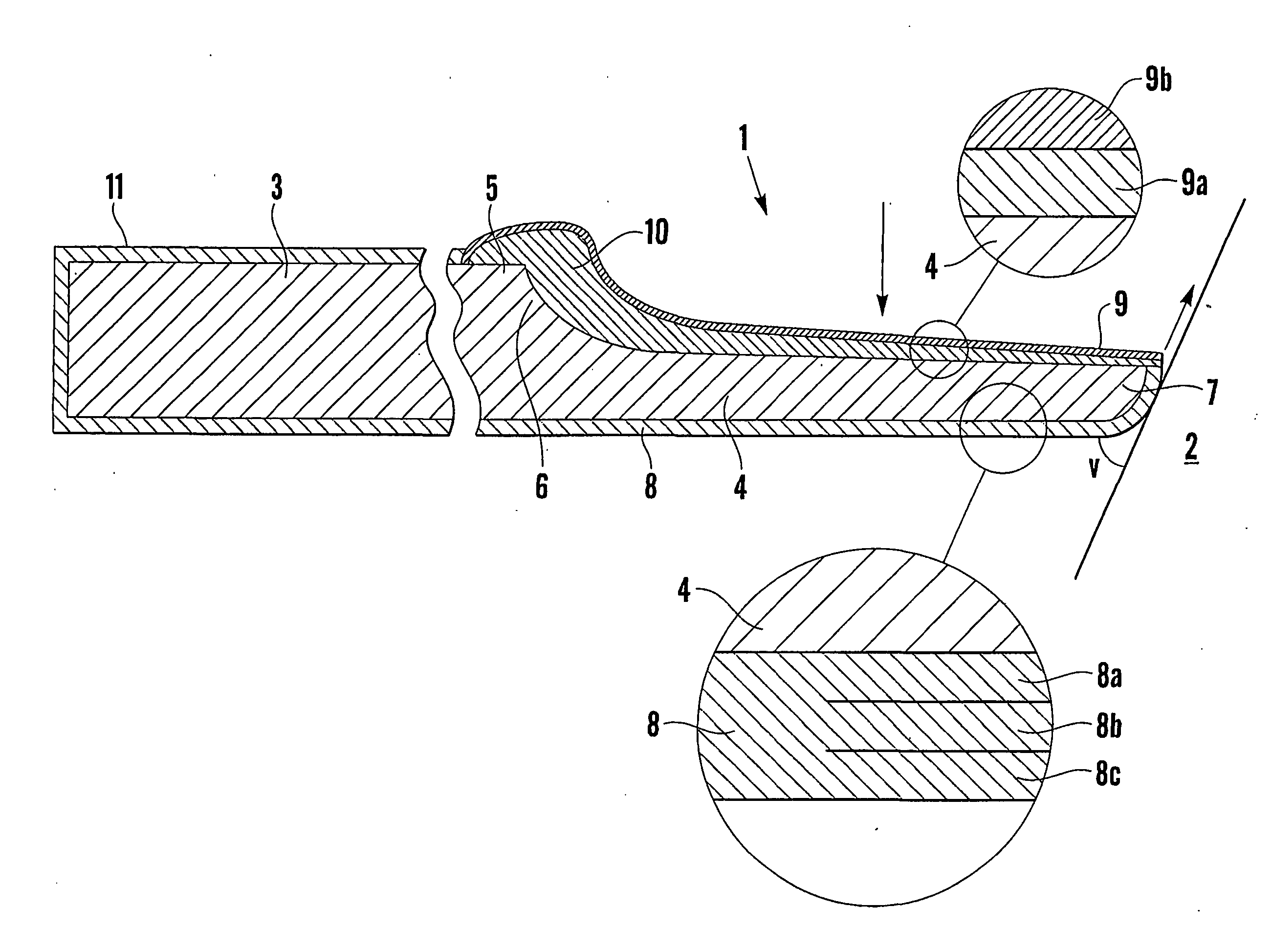
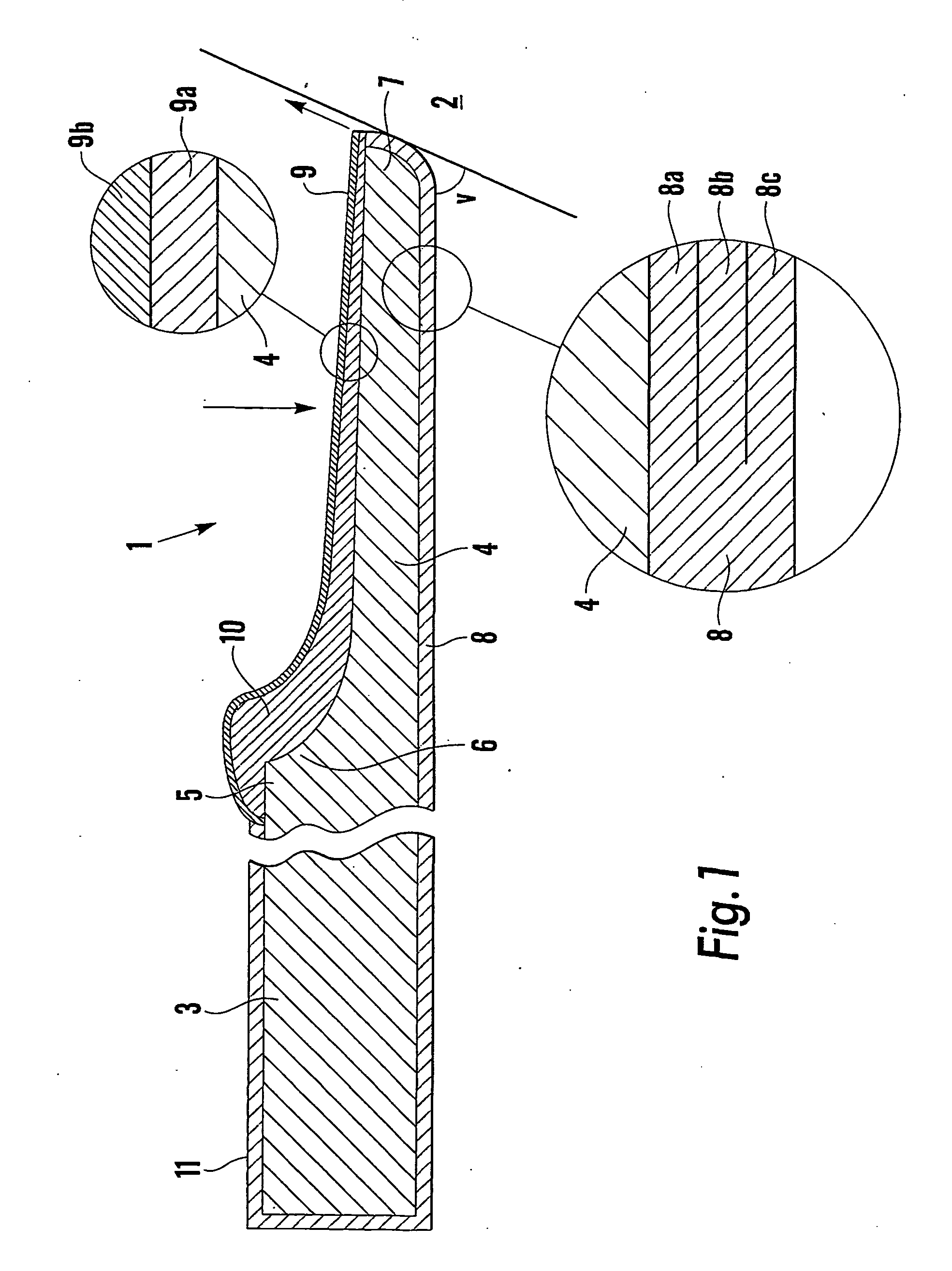
[0034] In the following, there is exemplified in table 1 a number of different conceivable variants of electrolytically coated blade according to the invention. By front part is meant the wear section and reinforcement section, the front part of the underneath side extending all the way to and including the reinforcement section which is arranged on the top side. By "Ni" is meant a nickel coating which has been created by aid of electrolytic nickel coating according to the description above. The coating layers used have been numbered so that layer 1 is the layer closest to the blade. By the designations is meant:

[0035] A Ni comprising abrasion resistant particles

[0036] L Ni comprising lubricating particles

[0037] T Ni comprising additives of the type Teflon / PTFE

[0038] AL Ni comprising both abrasion resistant and lubricating particles

[0039] W Ni without any additives

1 TABLE 1 Variant 1 2 3 4 5 6 7 8 Underneath side: Front part, layer 1 A A A L L L L L Front part, layer 2 L AL L A A A ...


PUM

PropertyMeasurementUnit
Angleaaaaaaaaaa
Fractionaaaaaaaaaa
Fractionaaaaaaaaaa

Abstract

The invention relates to a doctor or coater blade (1) of steel, having a nickel coating comprising abrasion resistant particles, said coating being constituted by an electrolytic nickel layer comprising abrasion resistant particles. The coating preferably comprises at least two electrolytic nickel layers having different composition, and may be formed differently in different sections of the blade. The invention also relates to a continuous process for electrolytic nickel coating in at least one electrolytic cell holding an electrolyte liquid comprising at least one nickel salt, and in at least one of these cells also comprising abrasion resistant particles.

Description

[0001] The present invention relates to a doctor or coater blade, having a nickel coating comprising abrasion resistant particles, e.g. SiC.PRIOR ART AND PROBLEMS[0002] Doctor and coater blades are used in the manufacturing of paper and in the printing industry, in order to scrape paper and printing ink, respectively, from a rotating roll. In this connection, problems with wear of the roll and of the doctor or coater blade, arise. The problem of wearing of a blade of doctor or coater type has been addressed in a number of patent applications, e.g. SE 8205805, SE 8205806 and SE 8205807, by the provision of a blade that has an abrasion resistant coating. However, this does not solve the problem of wear of the roll but rather increases this problem. For example at so called flexographic printing, the coater blade butts against a ceramic screen roll which is very expensive and which moreover gives rise to a quite considerable wear of the coater blade when the roll is new.[0003] Another ...

Claims


Application Information

Patent Timeline
IPC IPC(8): B05C11/04B41F9/10C23C28/00C23C28/04C25D5/14C25D15/02D21G3/00D21H23/34D21H25/10
CPCB05C11/045B41F9/1072B41N10/005C23C28/027Y10T428/12937C25D15/02D21G3/005D21H25/10Y10S428/935C25D5/14
Inventor LUNNERFJORD, ALLANSUNDBERG, ROLANDGAVEN, JAN-AKE
Owner SWEDEV
Why Eureka
Try Eureka