
Nuclear fusion reactor and method

a nuclear fusion and reactor technology, applied in nuclear reactors, nuclear explosives, greenhouse gas reduction, etc., can solve the problems of neutron damage, large energy needed to supply lasers, and inability to maintain effective plasma containment,

Inactive Publication Date: 2004-07-22
ENFINGER ARTHUR L
View PDF0 Cites 33 Cited by
  • Summary
  • Abstract
  • Description
  • Claims
  • Application Information

AI Technical Summary

Benefits of technology

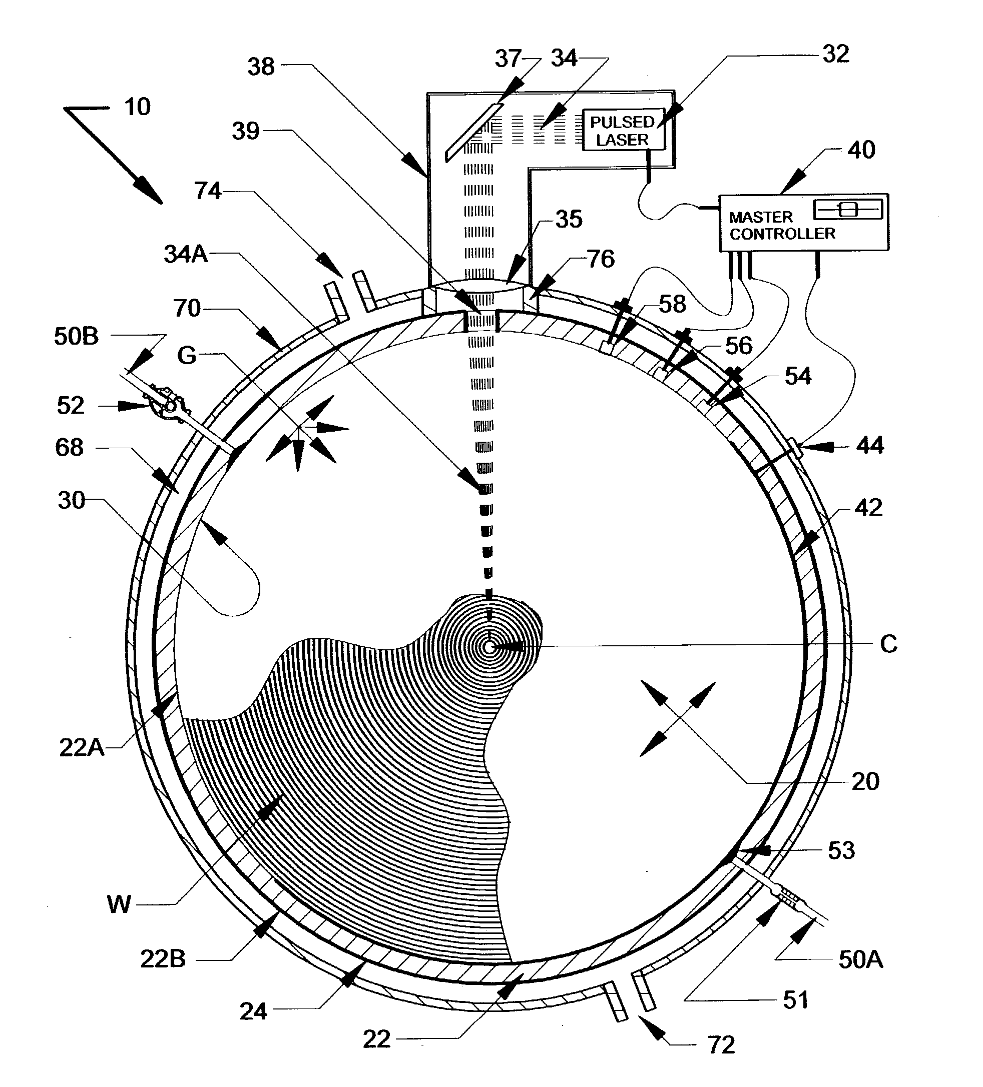
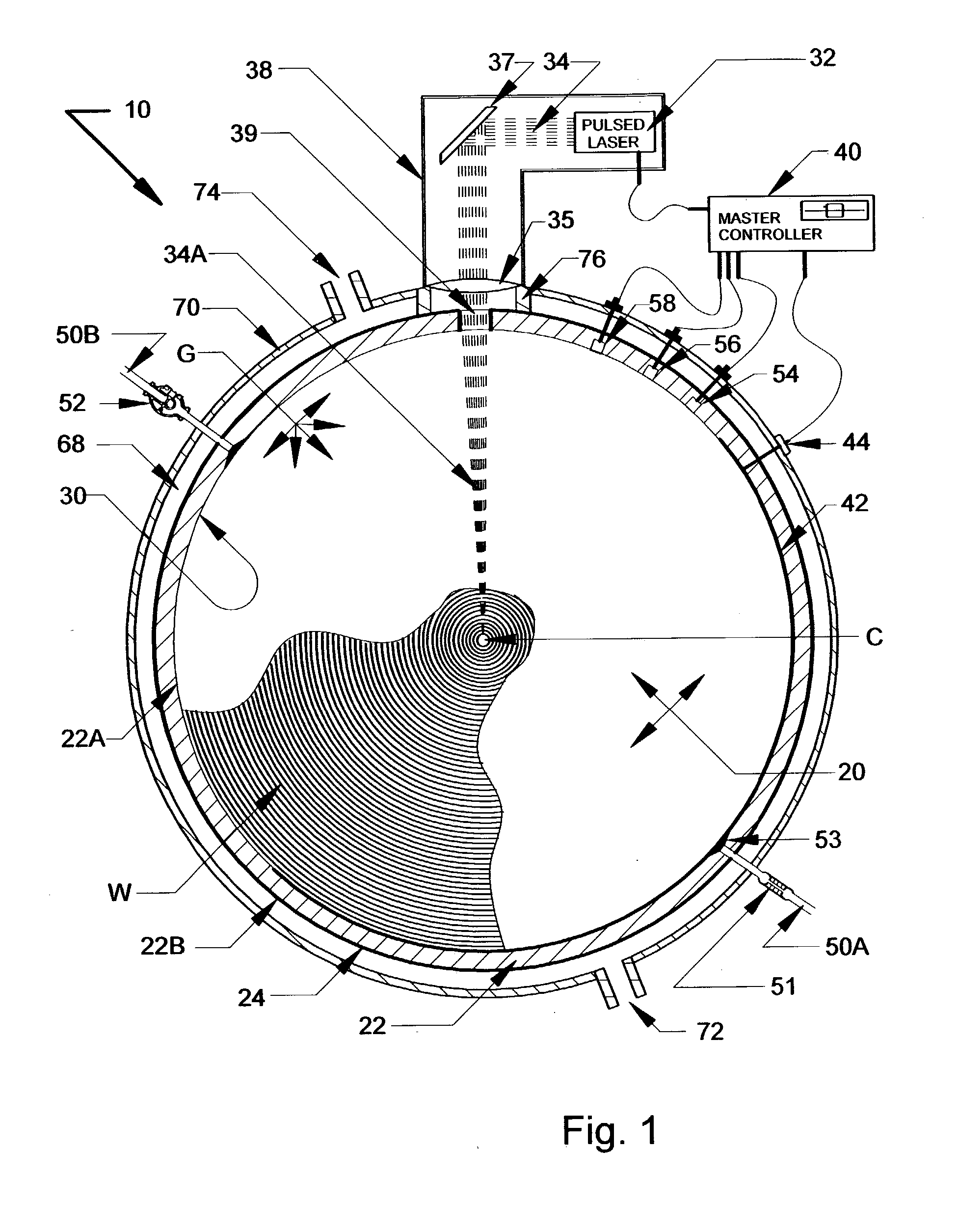
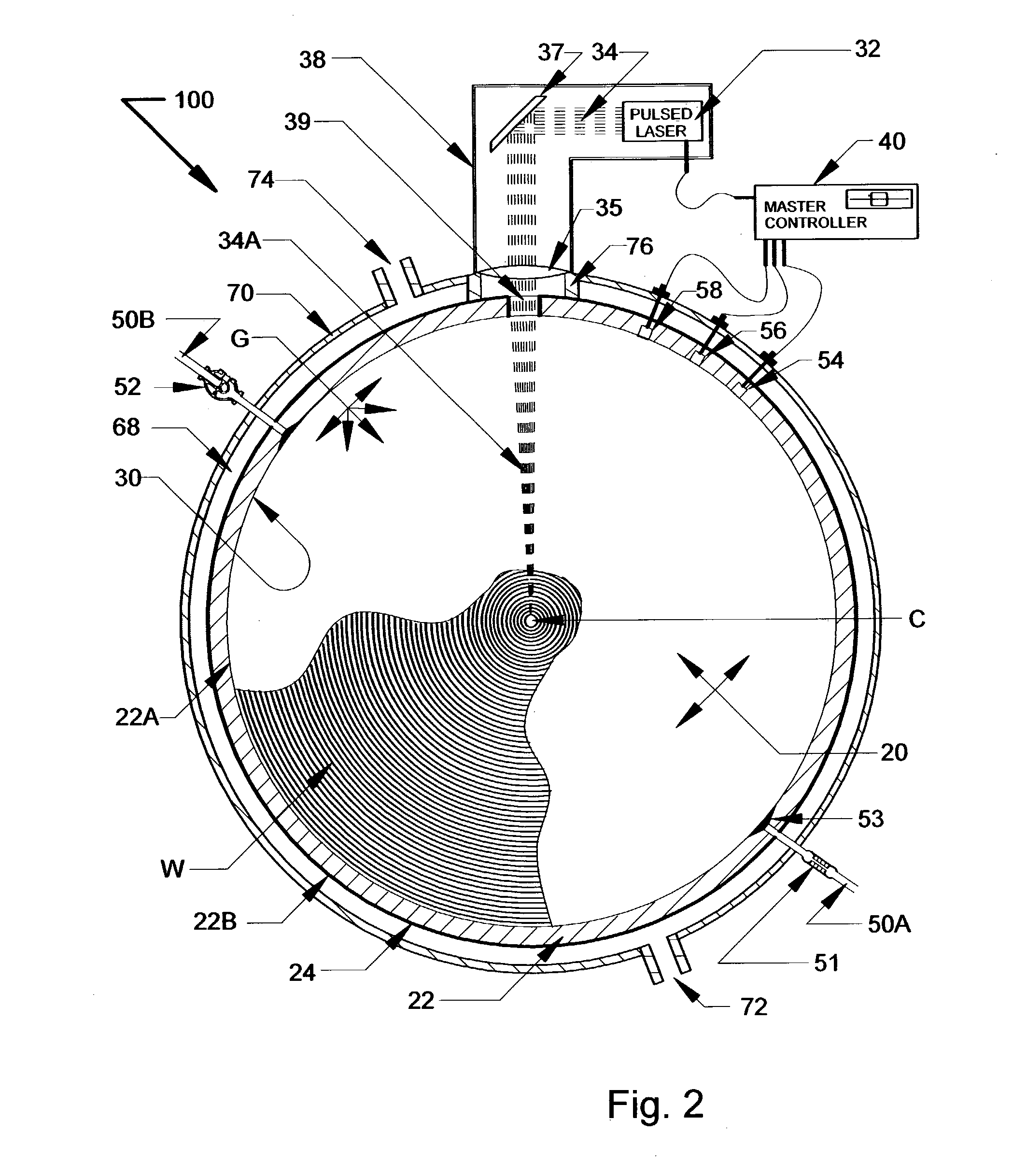
"The present invention is a fusion reactor that uses a spherical acoustic wave or standing wave pattern to create intense pressure and density at the center of a reaction chamber, where it triggers a spherical laser pulse that focuses on the high-density gas produced at the reaction chamber center, resulting in fusion ignition. The invention is different from previous fusion reactors in structure, methodology, and approach, and solves the problems with other reactors in a unique way. The invention contemplates a method of creating a fusion reaction by filling the reaction chamber with a nuclear fusible gas and activating the external pulsed laser or piezoelectric layer to create a spherical acoustic wave pattern centered within the reaction chamber."

Problems solved by technology

The major problem experienced with magnetic containment is maintaining effective plasma containment at ignition temperatures.
Problems with its present stage of development are associated with the complicated and cumbersome mechanics required for aiming and firing the lasers, the enormous energy needed to supply the lasers, energy recovery, and neutron damage.
While these two types of fusion reactors can eventually work, neither is adaptable for small scale energy production.
Feedback from a thermal sensor 56 in the chamber sphere wall could cause the master controller to stop or slow the reactor if chamber wall cooling was insufficient.
Operating a reactor at maximum drive without controls would quickly destroy the mirroring and partially melt the sphere wall as heat and radiation become too intense.

Method used


Image

  • Nuclear fusion reactor and method
  • Nuclear fusion reactor and method
  • Nuclear fusion reactor and method

Examples


Embodiment Construction

[0047] The following example describes the operation of a full-coverage piezoelectric driven fusion reactor with a reaction chamber two meters in diameter and similar in configuration to the reactor depicted by FIG. 3. The reaction chamber at start up contains deuterium at a pressure of 10 torr and a temperature of 300.degree. K. The speed of sound within the reactor chamber is about 930 m / s. Operating the piezoelectric drive at 100,000 Hz produces an acoustic wavelength of 0.93 cm. The converging forward pressure wave produced at the inner surface 22A has a depth in its direction of travel of one-half wavelength (0.465 cm). This forward pressure wave propagates inward, with constant speed, wavelength, and energy, and reinforces itself as a spherical pressure wave one-half wavelength in diameter (radius is 0.2325 cm) as it passes through the chamber center C. By comparing the volume of this wave at the chamber inner surface 22A, with its spherical volume as it reinforces at the cent...


PUM


Abstract

A nuclear fusion reactor comprising a spherical reaction chamber with a mirrored interior surface filled with a nuclear fusible and laser active gaseous medium such as deuterium. Using rapid gaseous expansion caused by a focused pulsed laser source and / or timed oscillations from piezoelectric transducer, a harmonic spherical acoustic wave pattern centered within the reaction chamber is created. This wave pattern is created near a desired frequency and centered in the sphere. The wave pattern contains a central gaseous ball of high-density, pressure, and temperature that causes ionization and radiation to occur. This radiation causes the mirrored chamber to activate a spherical laser effect focused on the high pressure plasma at the center of the reaction chamber. This spherical laser pulse acting on high pressure high-density of the central standing wave produces ignition of the gas and fusion. The tremendous energy from fusion drives the acoustic process which ideally allows for a self sustaining ignition temperature plasma requiring the addition of fuel only.

Description

[0001] 1. Field of the Invention[0002] This invention relates to energy production from nuclear fusion and in particular to a fusion reactor having a means for creating a spherical acoustic wave or standing wave pattern near a desired frequency and centered within a spherical mirrored reaction chamber. Radiation produced by intense heat as the waves focus and reinforce at the center of the reaction chamber will produce a spherical laser effect. The chamber becomes a self-contained pulsed spherical laser focused at the central acoustically compressed gas starting the fusion process.[0003] This invention is disclosed in my Disclosure Document No. 481620 filed Oct. 23, 2000.[0004] 2. Background of the Invention[0005] Controlled nuclear fusion has been a goal of scientists for several decades with billions of dollars spent to develop this energy resource. Two reactor types currently under large scale research and development involve the use of magnetic plasma containment and inertial la...

Claims


Application Information

Patent Timeline
Patent Type & Authority Applications(United States)
IPC IPC(8): G21B1/00
CPCY02E30/14Y02E30/18G21B3/00G21B1/03Y02E30/10
Inventor ENFINGER, ARTHUR L.
Owner ENFINGER ARTHUR L
Learn More