Anti-reflection spectacle lens and its production method

Inactive Publication Date: 2004-07-22
ASAHI KOGAKU KOGYO KK
View PDF5 Cites 63 Cited by
  • Summary
  • Abstract
  • Description
  • Claims
  • Application Information

AI Technical Summary

Benefits of technology

0007] Accordingly, an object of the present invention is to provide an anti-reflection spectacle lens having a water- and oil-repellent layer for preventing stains such as sweat, se

Problems solved by technology

Optical products such as spectacle lenses with strong reflection provide clear reflected image such as ghost and flare, failing to give clear visibility.
However, if the layers of silicon oxide or magnesium fluoride were washed with water and left to stand for drying without sufficiently wiping water off, the lens surfaces are stained with so-called "water spots," which are traces of water like stains remaining on the lens surfaces, resulting in deteriorated visibility.
Though the above water-repelling treatment to silicon oxide or magnesium fluoride constituting the surface layers of the anti-reflection films can prevent the water spots, it neither makes it difficult for stains such as sweat, sebum, dirt from hands, eye mucus, cosmetics, hairdressings, hair sprays, oils, etc. to at

Method used


Image

  • Anti-reflection spectacle lens and its production method
  • Anti-reflection spectacle lens and its production method
  • Anti-reflection spectacle lens and its production method

Examples


example 2

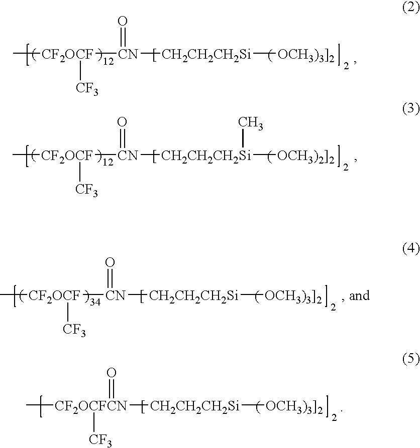
[0078] An anti-reflection spectacle lens 1 was produced in the same manner as in Example 1 except for changing the material of the water- and oil-repellent layer 8 to the compound represented by the above formula (3). The materials, optical thickness and refractive indexes of each layer of the anti-reflection film 10 and the water- and oil-repellent layer 8, and their vacuum deposition conditions are shown in Table 2, in which Layer No. represents the reference-numeral of each layer. The resultant anti-reflection spectacle lens was evaluated in the same manner as in Example 1. The results are shown in Table 4. This spectacle lens had the same anti-reflection function as that of a spectacle lens having no water- and oil-repellent layer 8.

2 TABLE 2 Composition and Properties of Layer Vacuum Deposition Conditions Optical Temperature Vacuum Layer Thickness Refractive of Substrate Degree Gas No. Material (nm) Index (.degree. C.) (Torr) Introduced 3 SiO.sub.2 193 1.462 80 1 .times. 10.sup...

example 3

[0079] An anti-reflection spectacle lens 1 was produced in the same manner as in Example 1 except for changing the material of the water- and oil-repellent layer 8 to the compound represented by the above formula (4). The materials, optical thickness and refractive indexes of each layer of the anti-reflection film 10 and the water- and oil-repellent layer 8, and their vacuum deposition conditions are shown in Table 3, in which Layer No. represents the reference numeral of each layer. The resultant anti-reflection spectacle lens was evaluated in the same manner as in Example 1. The results are shown in Table 4. This spectacle lens had the same anti-reflection function as that of a spectacle lens having no water- and oil-repellent layer 8.

3 TABLE 3 Composition and Properties of Layer Vacuum Deposition Conditions Optical Temperature Vacuum Layer Thickness Refractive of Substrate Degree Gas No. Material (nm) Index (.degree. C.) (Torr) Introduced 3 SiO.sub.2 193 1.462 80 1 .times. 10.sup...


PUM

PropertyMeasurementUnit
Thicknessaaaaaaaaaa
Temperatureaaaaaaaaaa
Angleaaaaaaaaaa

Abstract

An anti-reflection spectacle lens has an anti-reflection film composed of a plurality of layers formed on at least one surface of a lens substrate or other one or more layers formed on said lens substrate, the anti-reflection film comprising an outermost layer made of silicon oxide, on which a water- and oil-repellent layer is formed by vacuum deposition. The spectacle lens is excellent in water and oil repellency, and aqueous stains and oily stains attached to the spectacle lens can easily be wiped off. The use of a pellet impregnated with a hydrophobic, reactive organic compound in a vacuum deposition chamber contributes to the reduction of a production cost.

Description

[0001] The present invention relates to an anti-reflection spectacle lens having a water- and oil-repellent layer, and a method for producing such an anti-reflection spectacle lens.[0002] Optical products such as spectacle lenses with strong reflection provide clear reflected image such as ghost and flare, failing to give clear visibility. To prevent such reflection, anti-reflection films are generally formed on the spectacle lenses.[0003] The anti-reflection films generally have single- or multi-layer structures, which are formed on the spectacle lenses by physical treatments. The anti-reflection films are usually provided with surface layers composed of silicon oxide or magnesium fluoride having high hardness and low refractive indexes. However, if the layers of silicon oxide or magnesium fluoride were washed with water and left to stand for drying without sufficiently wiping water off, the lens surfaces are stained with so-called "water spots," which are traces of water like stai...

Claims


Application Information

Patent Timeline
IPC IPC(8): C03C17/30G02C7/02C03C17/42C23C14/12C23C14/24C23C28/00G02B1/10G02B1/11
CPCC03C17/30C03C17/42C03C2217/76C23C14/12G02B1/111C23C14/243C23C28/00G02B1/105C23C14/24Y10T428/3154Y10T428/31663G02B27/0006G02C7/02G02B1/18
Inventor TAKUSHIMA, HIDENORI
Owner ASAHI KOGAKU KOGYO KK
Why Eureka
Try Eureka