
Carrier-phase-based relative positioning device

a relative positioning and carrier technology, applied in measurement devices, satellite radio beaconing, instruments, etc., can solve the problems of waste of already accumulated data, inability to directly measure the integral part of the phase difference, and inability to receive the radio waves transmitted from the gps satellite with the antenna, etc., and achieve the effect of quick determination and eas

Inactive Publication Date: 2004-07-29
FURUNO ELECTRIC CO LTD
View PDF4 Cites 33 Cited by
  • Summary
  • Abstract
  • Description
  • Claims
  • Application Information

AI Technical Summary

Benefits of technology

[0016] According to the invention, a carrier-phase-based relative positioning device comprises means for estimating an integer ambiguity and a baseline vector and means for verifying the integer ambiguity, wherein a new integer ambiguity is estimated from the previously estimated baseline vector or integer ambiguity when the number of positioning satellites has changed or when a positioning satellite used as a reference (reference satellite) has been switched. When the number of positioning satellites has changed or when the reference satellite has been switched, the positioning device thus constructed can continue estimation of the integer ambiguity using the integer ambiguity or the baseline vector which has so far been determined without the need to estimate the integer ambiguity from the beginning. Accordingly, it becomes unnecessary to newly estimate the integer ambiguity from a single or double phase difference so that the integer ambiguity can be quickly determined with ease.
[0017] In-one feature of the invention, when the number of positioning satellites has increased, the new integer ambiguity is estimated from the baseline vector estimated before the number of positioning satellites has increased. With this arrangement, the positioning device can continue estimation of the integer ambiguity without interrupting estimation process carried out up to the point of change in the number of positioning satellites, using also radio waves received from a newly observed positioning satellite. Thus, the positioning device can easily and uninterruptedly estimate the integer ambiguity even when the number of positioning satellites has increased.
[0018] In another feature of the invention, when the number of positioning satellites has decreased, the new integer ambiguity is estimated by removing an estimated value of the integer ambiguity derived from the positioning satellite which has become unobservable. With this arrangement, the positioning device can continue estimation of the integer ambiguity without interrupting estimation process carried out up to the point of change in the number of positioning satellites, excluding information derived from the positioning satellite which has become unobservable. Thus, the positioning device can easily and uninterruptedly estimate the integer ambiguity even when the number of positioning satellites has decreased.
[0019] In another feature of the invention, a double phase difference is used for estimating the integer ambiguity and, when the reference antenna has been switched, the integer ambiguity after the switching of the reference antenna is estimated by using a difference operation method for calculating the integer ambiguity and the baseline vector in response to the reference antenna switching. This arrangement makes it possible to easily estimate the integer ambiguity by reference to the baseline vector obtained immediately before reference antenna switching.
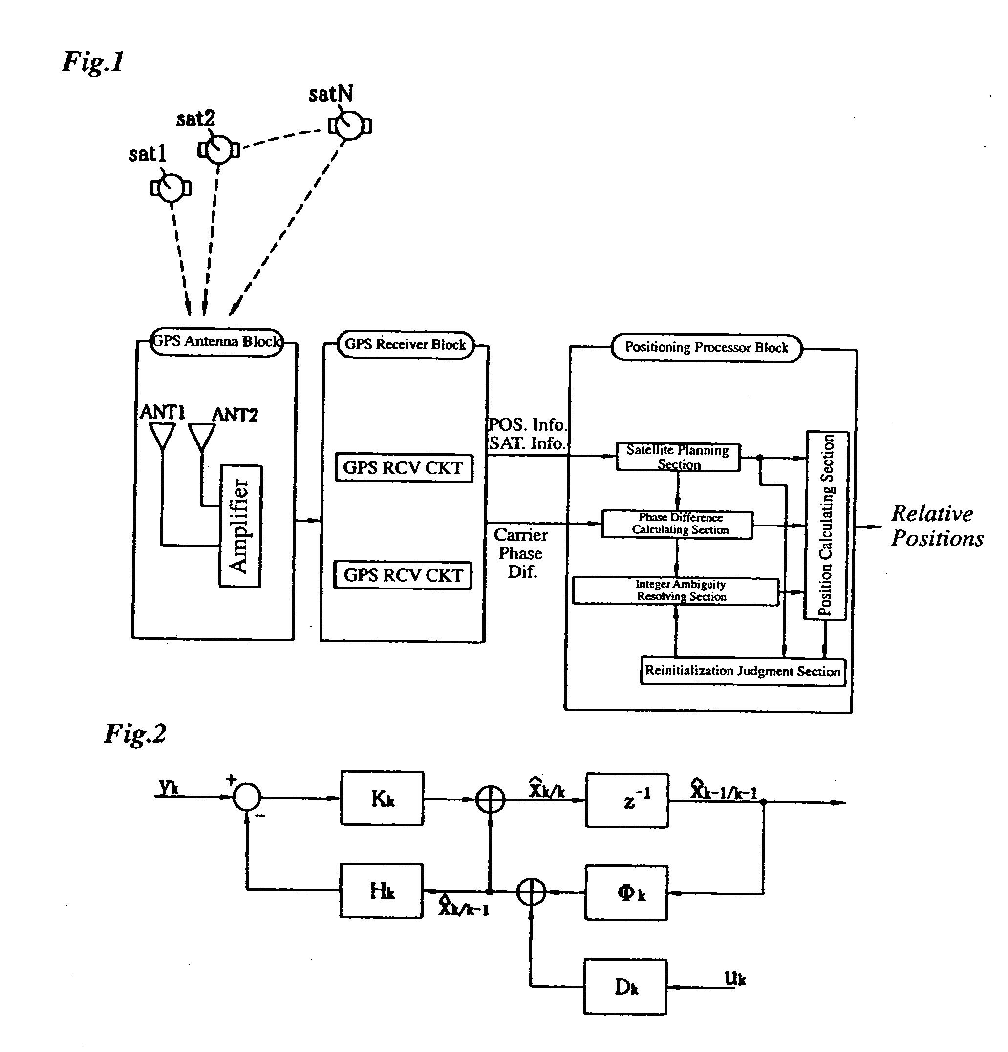
[0022] In still another feature of the invention, the positioning device uses a Kalman filter for estimating a floating ambiguity and the baseline vector from which the integer ambiguity is determined. This arrangement makes it possible to simultaneously estimate and calculate the floating ambiguity and the baseline vector with improved reliability.
[0023] In yet another feature of the invention, the means for estimating and determining candidates of the integer ambiguity based on the floating ambiguity uses lambda notation. This arrangement makes it possible to easily estimate and calculate the integer ambiguity with improved reliability.

Problems solved by technology

It is however impossible to directly measure the integral part of the phase difference by the positioning apparatus.
When the elevation of the GPS satellite varies from a high angle to an angle less than a specific value, it would become no longer possible to receive the radio waves transmitted from the GPS satellite with the antennas.
This is time-consuming and results in a waste of already accumulated data.
In the double phase difference method, it becomes impossible to estimate the integer ambiguity value when it becomes impossible to receive radio waves from the reference satellite.
When the elevation of the reference satellite becomes low, for example, it would become impossible for the antennas to receive the radio waves from the reference satellite, making it impossible to calculate the double phase difference.
Again, it becomes impossible in this case to continue estimation of the integer ambiguity value, making it necessary to recalculate the integer ambiguity from the beginning.
This kind of error is likely to occur when the number of GPS satellites is small.
Such errors could more or less occur in verifying the candidates of the true integer ambiguity no matter what kind of currently available verification process is used.
A stringent verification process results in an extended measuring time, however.
This, however, results in poorer accuracy.
Thus, the positioning device can easily and uninterruptedly estimate the integer ambiguity even when the number of positioning satellites has increased.
Thus, the positioning device can easily and uninterruptedly estimate the integer ambiguity even when the number of positioning satellites has decreased.

Method used


Image

  • Carrier-phase-based relative positioning device
  • Carrier-phase-based relative positioning device
  • Carrier-phase-based relative positioning device

Examples


first embodiment

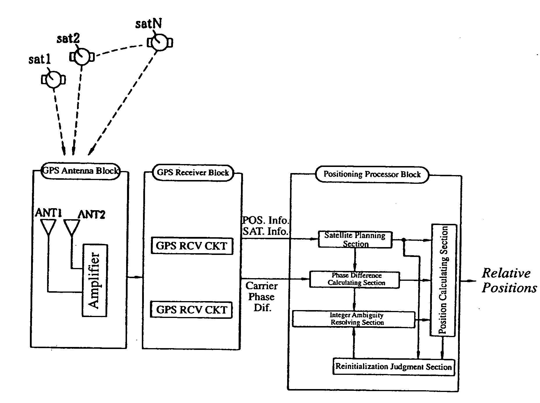
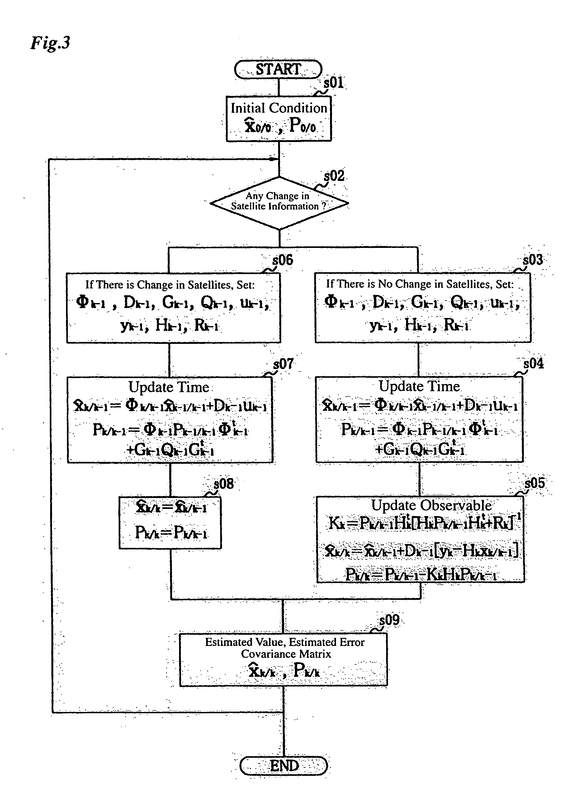
[0030] First, a carrier-phase-based relative positioning device according to the invention is described with reference to FIGS. 1 to 3.

[0031] FIG. 1 is a block diagram of the carrier-phase-based relative positioning device of the first embodiment, in which designated by the symbols sat1, sat2 and satN are GPS satellites (positioning satellites).

[0032] A GPS receiver block including two antennas ANT1, ANT2 receives radio waves transmitted from the GPS satellites sat1, sat2, satN, downconverts received signals into intermediate frequency (IF) signals. The IF signals are amplified by an amplifier built in the GPS receiver block and delivered to a GPS receiver block.

[0033] Based on the signals received by the individual antennas ANT1, ANT2, the GPS receiver block calculates the positions of the antennas ANT1, ANT2 and carrier phase differences, and sends these data together with information on the individual GPS satellites sat1, sat2, satN to a positioning processor block at specific ti...

second embodiment

[0102] Next, the configuration of a carrier-phase-based relative positioning device according to the invention is described.

[0103] (1) When the number of positioning satellites increases

[0104] In this case, floating ambiguities and baseline vectors are estimated using the same method as in the first embodiment.

[0105] (2) When the number of positioning satellites decreases

[0106] In this case, the filter equation is expressed as follows: 11 [ b k + 1 a k + 1 ] =[I O OT 1 ] [ b k a k ] + [ w bk w ak ] ( 20 )

[0107] where T.sub.1 is a matrix obtained by multiplying a row of a unit matrix I corresponding to a positioning satellite which has become unobservable by 0. As an example, when one (corresponding to the third row) of 12 positioning satellites which could be observed becomes unobservable, the matrix T.sub.1 is expressed as follows, wherein every element of the third row of the unit matrix is multiplied by 0. 12 T 1 = [1 0 0 0 0 0 0 0 0 0 0 0 0 1 0 0 0 0 0 0 0 0 0 0 0 0 0 0 0 0 0 0 ...

third embodiment

[0120] Next, the configuration of a carrier-phase-based relative positioning device according to the invention is described.

[0121] While the aforementioned first and second embodiments employ the Kalman filter for estimating only the baseline vector b.sub.k and the floating ambiguity a.sub.k, the third embodiment employs a Kalman filter capable of estimating not only the baseline vector b.sub.k and the floating ambiguity a.sub.k but also a multipath error v.sub.k, which is observation noise, at the same time.

[0122] In this case, the filter equation representing time update is expressed as follows:

[0123] (1) When there is no change in the satellite information 15 [ b k + 1 a k + 1 v k + 1 ] = [ B k + 1 +O B k + 1 + O I O O O ( 1 -) I ][ b k a k v k ] + [ B k + 1 +( y k + 1 - y k ) o o] + [ w bk w ak w vk ] ( 27 )

[0124] where B.sub.k+1.sup.+=(B.sub.k+1.sup.tB.sub.k+1).sup.-1B.sub.k+1.su-p.t and .alpha. is a constant representing a property of multipath errors.

[0125] Mathematical opera...


PUM


Abstract

A carrier-phase-based relative positioning device employs a signal processing method which makes it possible to continue estimation of integer ambiguity values even when the number of positioning satellites has changed, determine an integer ambiguity value by efficiently verifying the integer ambiguities in a short time, and calculate a baseline vector. The positioning device includes an integer ambiguity resolving section which determines integer ambiguities of single or double phase differences using a Kalman filter and lambda notation. The Kalman filter is used to calculate estimated values of floating ambiguities and the lambda notation is used to calculate estimated values of the integer ambiguities based on the floating ambiguities. A candidate of a potentially true integer ambiguity that is considered most reliable is determined through various verification processes. When the number of positioning satellites has increased or decreased, or when a reference satellite has been switched, a floating ambiguity after the change in satellite information is estimated from a baseline vector estimated before the change.

Description

BACKGROUND OF THE INVENTION AND RELATED ART STATEMENT[0001] 1. Field of the Invention[0002] The present invention relates generally to a carrier-phase-based relative positioning device used in such apparatus as a global positioning system (GPS) compass which determines geographic direction from multiple relative position fixes obtained by using the phases of carrier signals received from GPS satellites or a real-time kinematic (RTK) GPS receiver which determines relative positions in real time by using the carrier phases of the GPS signals.[0003] 2. Description of the Prior Art[0004] There exists a known method of determining relative positions by receiving radio signals transmitted from GPS satellites with multiple antennas and measuring the carrier phases of the signals. This method is conventionally used in an apparatus which determines relative positions of a mobile vehicle, such as a vessel.[0005] Relative positions are determined in a manner described below in this kind of pos...

Claims


Application Information

Patent Timeline
Patent Type & Authority Applications(United States)
IPC IPC(8): G01S5/14G01S19/22G01S19/44
CPCG01S19/36G01S19/55G01S19/44
Inventor TODA, HIROYUKIFUJISAWA, NAOMIFUKUDA, MASARU
Owner FURUNO ELECTRIC CO LTD
Learn More