Manufacturing method for ferrite type magnets

a technology of ferrite and manufacturing method, applied in the field of permanent magnets, can solve the problems of high cost of substitution elements la and co, high cost of la and co, and high cost of lanthanum

Inactive Publication Date: 2004-08-05
UGIMAG SA
View PDF3 Cites 10 Cited by
  • Summary
  • Abstract
  • Description
  • Claims
  • Application Information

AI Technical Summary

Benefits of technology

[0051] In fact, she noted that, in the case of green granules according to the invention, the magnetic performances of the magnets were better when the apparent density da of the clinkers B formed were comprised between 2.5 and 3.5.
[0055] Thus, the applicant developed a process which cumulates the advantages of the two methods known in the present state of the art, without having the disadvantages, and which makes it possible to form a clinker with both a high homogeneity of size and chemical structure and with a high level of magnetoplumbite phase.
[0056] This method according to the invention is thus a combination of two means, one of which concerns the homogeneity of the chemical composition of the green granules A to be calcinated and therefore that of the clinker B formed after calcination--the size or size-distribution of the green granules A being little modified during calcination, and the other of which concerns control of the calcination of the green granules A, not by the temperature itself but by the apparent density of the clinker B formed, these two means having been diagnosed as essential by the applicant, for improving the value of the anisotropy field Ha and the final magnetic properties of the magnets.
[0058] It is well known that the measurements of temperatures in continuous rotary furnaces, carried out typically by optical pyrometers, are relatively imprecise, less as far as the measurement itself is concerned, than for the very heterogeneous temperature distribution in each of the portions of space or volume of the furnace. It is therefore very advantageous to be able to pilot a furnace without using this type of temperature measurement, even though temperature measurements are still used, in particular for verifying continuously and in real time the stability of operation of the furnace.
[0059] As will be shown in the comparative tests, the results obtained with the method according to the invention have shown a very clear improvement in the magnetic performance of magnets E and F, all other things being equal, which allows one to consider that the hypotheses of the applicant are valid without any doubt.

Problems solved by technology

The major problem of magnets according to the state of the art described above is their very high cost.
In fact, the substitution elements La and Co are very expensive, lanthanum being much more expensive than strontium, and cobalt oxide being about 200 times more expensive than iron oxide.

Method used


Image

  • Manufacturing method for ferrite type magnets
  • Manufacturing method for ferrite type magnets
  • Manufacturing method for ferrite type magnets

Examples


examples of embodiments

[0107] General Description of Tests

[0108] Six series of tests were carried out (tests numbered 1a, 1b, 1c to 6a, 6b and 6c) as well as 4 complementary tests (tests numbered 7 to 10), which differ by the chemical composition or the calcination temperature.

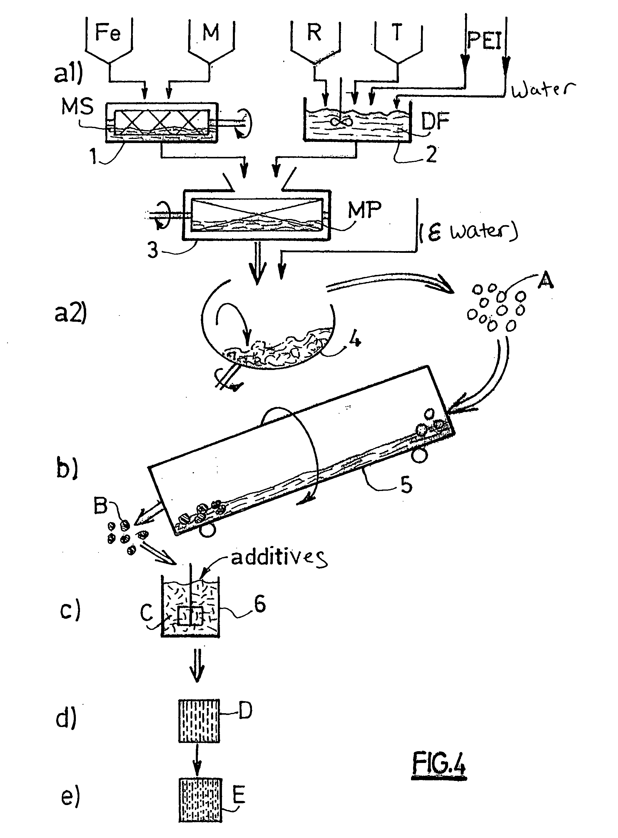
[0109] For each series of tests, one started with the same raw materials providing the elements Fe, M, R and T, and manufactured 3 mixtures of the same chemical composition:

[0110] one according to all or part of the method according to the invention: tests 1c, 3c and 5c according to the invention and tests 2c, 4c and 6c according to a part of the invention,

[0111] one according to the wet process of the state of the art: tests 1a to 6a,

[0112] and one according to the dry process of the state of the art: tests 1b to 6b.

[0113] For a same test series, one formed, at stage b), clinkers B under the same conditions, in particular with the same calcination temperature.

[0114] The method according to the invention is basically described, in i...


PUM

PropertyMeasurementUnit
particle sizeaaaaaaaaaa
sizesaaaaaaaaaa
pressureaaaaaaaaaa

Abstract

A method for making ferrite magnets of formula M1-xRxFe12-yTyO19 including: a1) forming a powder mixture MP of related raw materials, a2) transforming into granules in green state A, b) calcining the granules in green state to form clinker B, c) wet ding clinker B to obtain a homogeneous dispersion of fine particles C, d) concentrating and compressing the particles under an orienting magnetic field to form an anisotropic green compact D, and e) sintering the green compact to obtain a sintered element E. In step a1), MP is formed from a dry mixture MS of M and Fe powder elements and a dispersion DF of raw materials related to elements R and T, and in step b) the granules in green state are calcined to obtain a clinker B which is homogeneous in chemical composition and size and with apparent low density, between 2.5 and 3.5.

Description

[0001] The invention relates to the field of permanent magnets, and more particularly to magnets of the ferrite type comprising the magnetoplumbite type.STATE OF PRIOR ART[0002] The present invention relates to permanent magnets of the ferrite type based on the magnetoplumbite phase MFe.sub.12O.sub.19 with M=Sr,Ba,etc . . . , in which the element M is partially substituted by an element R chosen from among the rare earths or bismuth, and in which the element Fe is partially substituted by at least one transition metal T.[0003] Such magnets are already known for their high magnetic properties, as disclosed in the Japanese patent application J10-149910 or in the European patent application EP-0 905 718 or in the international patent application WO99 / 34379.[0004] In these patent applications, lanthanum La is generally used as the element M, and cobalt Co as element R.[0005] Manufacture of such magnets comprises the following stages:[0006] a) formation of a mixture of raw materials eith...

Claims


Application Information

Patent Timeline
Patent Type & Authority Applications(United States)
IPC IPC(8): C04B35/26H01F1/08H01F1/11H01F41/02
CPCH01F41/0273C04B35/2633C04B35/26
Inventor TENAUD, PHILIPPEBRANDO, ERIC
Owner UGIMAG SA
Why Eureka
Try Eureka