
Electroluminescent devices

a technology of electroluminescent devices and electrodes, which is applied in the direction of discharge tube luminescnet screens, natural mineral layered products, etc., can solve the problems of preventing the efficient injection of carriers into the light-emitting layer, material has never been used in small molecule organic el devices, and the impurity likely to form traps should not be produced

Inactive Publication Date: 2004-08-05
INTELLECTUAL VENTURES II
View PDF25 Cites 28 Cited by
  • Summary
  • Abstract
  • Description
  • Claims
  • Application Information

AI Technical Summary

Problems solved by technology

The reason for the low luminance of the early organic EL devices is the highly resistive EL medium, which prevents the efficient injection of carriers into the light-emitting layer.
The thermally induced deformation of the hole-transporting materials is thought to be one of the main causes of degradation.
However, these materials have never been used in small molecule organic EL devices.
Moreover, the impurities likely to form traps should not be produced during preparation or use.

Method used


Image

  • Electroluminescent devices
  • Electroluminescent devices
  • Electroluminescent devices

Examples


example 1

[0083] Synthesis of 1,2-bis(benzoyl)-1,2-dibromoethylene{1,2-bis(benzolyl--1,2-dibromoethane}

[0084] 1,2-bisbenzoyl-ethylene (C.sub.16H.sub.12O.sub.2: 236.27, 5.5 g, 23.3 mmol) was dissolved in 40 ml CHCl.sub.3, to which was added a solution of bromine (FW: 159.81, d=3.1023, 1.2 ml, 23.3 mmol) in CHCl.sub.3 (8 ml). The reaction mixture was stirred under an atmosphere of nitrogen for 30 min and concentrated under reduced pressure to give a white solid. After recrystallization from ether / EtAc, the yield was 7.2 g (78.4%).

example 2

[0085] Synthesis of 1,2-bis(benzolyl)acetylene

[0086] To a solution of 1,2-bisbenzoyl-1,2-dibromoethylene (C.sub.16H.sub.12O.sub.2Br.sub.2: 396.08, 6 g, 15.15 mmol) in reagent-grade acetone (150 ml) under an atmosphere of nitrogen was added triethylamine (C.sub.6H.sub.15N, 101.19, d=0.72, 4.4 ml, 30.30 mmol). After stirring the reaction mixture for 10 min at reflux temperature, the quaternary salt was filtered and the filtrate concentrated under reduced pressure. After recrystallization from ethanol, the yield was 3.02 g (yellow color, 85%).

example 3

[0087] Synthesis of 1,2-bis(benzoyl)-3,4,5,6-tetraphenylbenzene

[0088] 1,2-bis(benzoyl)acetylene (C.sub.16H.sub.10O.sub.2, 234.27, 2 g, 8.54 mmol), tetraphenylcyclopenta-dienone (C.sub.29H.sub.20O, 384.47, 3.28 g, 8.54 mmol), and 40 g benzophenone were refluxed for 2 hr under an atmosphere of nitrogen. The reaction mixture was cooled to 30.degree. C. and poured into a large volume (250 ml) of methanol. The tan precipitation was washed with methanol (2.times.10 ml) and refluxed in toluene (25 ml) charcoal (a spoon) to give a white crystal in 43% yield.


PUM

PropertyMeasurementUnit
Fractionaaaaaaaaaa
Fractionaaaaaaaaaa
Lengthaaaaaaaaaa

Abstract

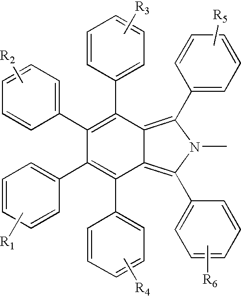
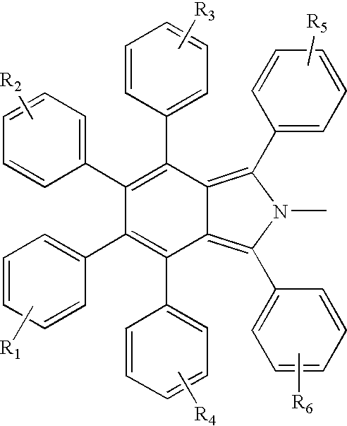
A compound of formula [I]: X-R [I] wherein X represents the group: and R is either (i) represented by the formula [II] wherein n is 1 or 2, and the or each R7 group is independently selected from the group consisting of hydrogen and halogen atoms, cyano, nitro, mercapto, carbonyl and sulfone groups, and optionally substituted alkyl, haloalkyl, hydroxyalkyl, aryl, alkoxy, aryloxy, alkylamino, arylamino, alkylthio, arylthio, ester, siloxy, cyclic hydrocarbon and heterocyclic groups; or (ii) is selected from the group consisting of optionally substituted alkyl, hydroxyalkyl, aryl, cyclic hydrocarbon and heterocyclic groups; wherein in each case R1-R6 are each independently selected from the group consisting of hydrogen and halogen atoms, cyano, nitro, mercapto, carbonyl and sulfone groups, and optionally substituted alkyl, haloalkyl, hydroxyalkyl, aryl, alkoxy, aryloxy, alkylamino, arylamino, alkylthio, arylthio, ester, siloxy, cyclic hydrocarbon and heterocyclic groups. The compounds are useful as hole-transporting materials in electroluminescence devices.

Description

[0001] This invention relates to organic electroluminescence (EL) devices and, more particularly, to the use of novel highly phenylated isoindole derivatives for thin-film type organic electroluminescence devices with good thermal and chemical stabilities.BACKGROUND TO THE INVENTION[0002] In the 1960s, many trials for the preparation of an organic electroluminescence device were reported using conjugated materials generally having fused aromatic rings (U.S. Pat. No. 3,172,862, issued 1965; U.S. Pat. No. 3,173,050, issued 1965). The efficiencies and lifetimes of these organic EL devices were much lower than those obtained from inorganic systems at the same time, so research mainly focused on the inorganic materials. The reason for the low luminance of the early organic EL devices is the highly resistive EL medium, which prevents the efficient injection of carriers into the light-emitting layer. Tang and VanSlyke solved this problem successfully in the late 1980s (Tang and VanSlyke, A...

Claims


Application Information

Patent Timeline
IPC IPC(8): C07D209/48C07D209/88C09K11/06H01L51/50H05B33/14
CPCC07D209/48C07D209/88C09K11/06Y10S428/917H01L51/5048H05B33/14C09K2211/1029H10K50/14
Inventor LEE, SHUIT-TONGLEE, CHUN-SINGWANG, PENG-FEIMI, BAO-XIU
Owner INTELLECTUAL VENTURES II
Learn More