Flame-less infrared heater

a flameless, infrared heater technology, applied in the direction of gaseous heating fuel, combustion type, stove or range, etc., can solve the problems of high cost of electric heaters, high cost of catalytic heaters, high concentration of unburned hydrocarbons and carbon monoxide,

Inactive Publication Date: 2004-08-05
GAS TECH INST
View PDF11 Cites 45 Cited by
  • Summary
  • Abstract
  • Description
  • Claims
  • Application Information

AI Technical Summary

Problems solved by technology

The primary reason for not using gas-fired infrared is due to operating temperature and control limitations of available gas heaters.
Electric heaters are intrinsically expensive to operate while catalytic heaters, in addition to being expensive, produce high concentrations of unburned hydrocarbons and carbon monoxide.
In addition, a glowing flame is very prominent over the mesh as a result of which the heat flux distribution is highly irregular and non-uniform, particularly for larger scale heaters with large re-radiating surfaces.
In comparison to conventional infrared heating systems in whic

Method used


Image

  • Flame-less infrared heater
  • Flame-less infrared heater

Examples


Embodiment Construction

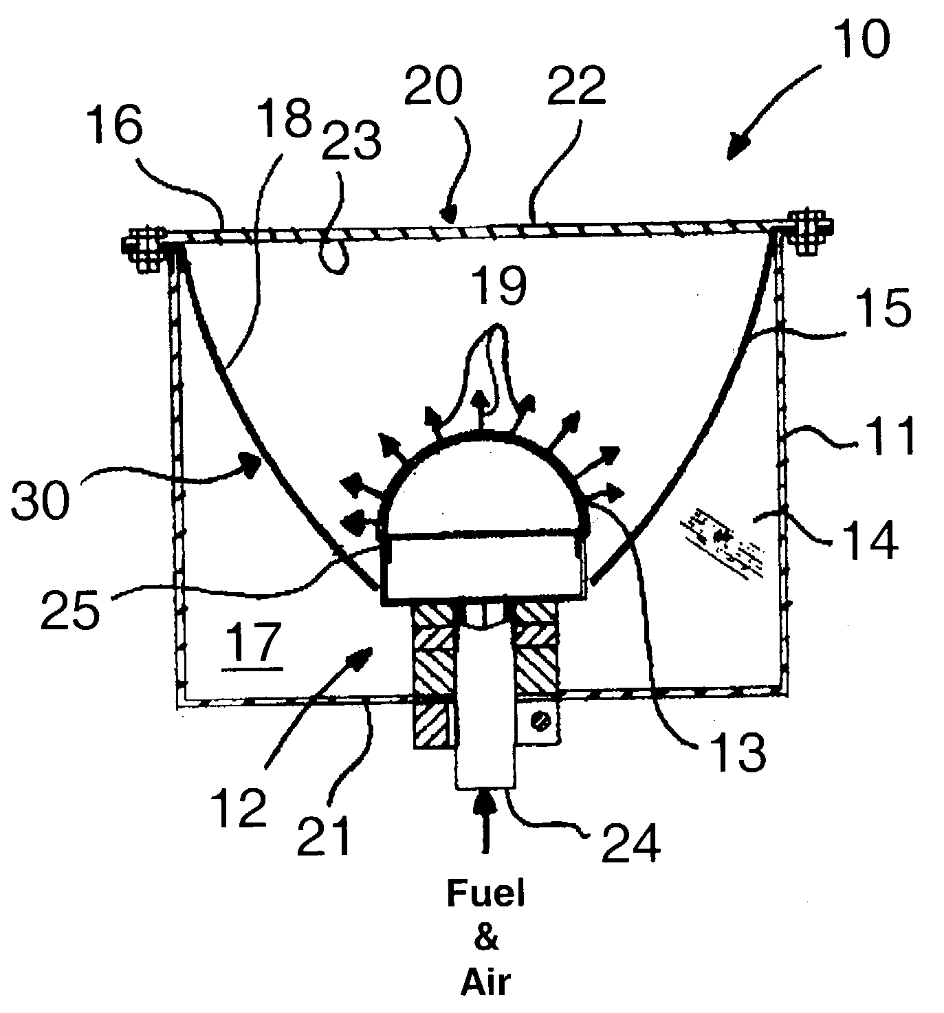
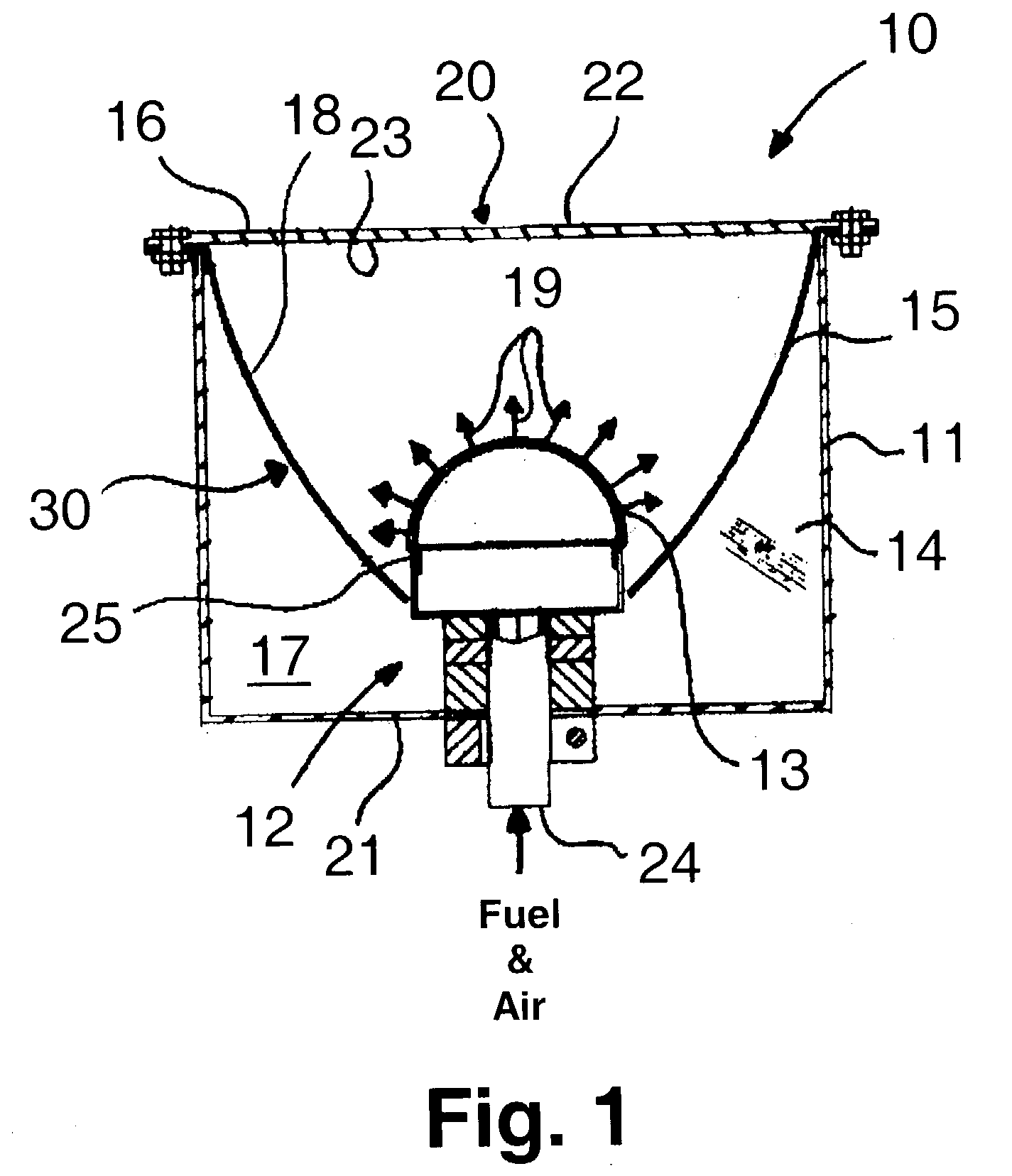
[0019] The heating apparatus of this invention is fired with a gaseous hydrocarbon fuel, preferably natural gas, and produces radiant heat in the wavelength range of about 1 to 10 micrometers. The thermal and combustion characteristics are comparable to conventional IR radiant heaters, including low-to-medium flux gas fired heaters, catalytic heaters and electric heaters, providing a radiating surface temperature in the range of about 700.degree. F. to about 1500.degree. F. The apparatus is suitable for use in most heating, drying and curing applications requiring a firing rate in the range of about 4,000 to about 40,000 Btu / hr-ft.sup.2.

[0020] As shown in FIG. 1, heating apparatus 10 in accordance with one embodiment of this invention comprises a housing 11 having a bottom region 17 or burner side 21 and a radiant energy output side 20, which radiant energy output side 20 is disposed opposite from the bottom region 17 or burner side 21. Radiant energy output side 20 comprises at lea...


PUM

PropertyMeasurementUnit
Angleaaaaaaaaaa
Temperatureaaaaaaaaaa
Surface areaaaaaaaaaaa

Abstract

A heating apparatus including a housing having a radiant energy output side and an oppositely disposed burner side. The radiant energy output side includes at least one re-radiating surface. Disposed within the housing proximate the burner side and having a burner outlet facing the radiant energy output side is a burner. At least one concave reflector is disposed around the burner and is oriented to reflect heat from said burner toward said radiant energy output side of said housing.

Description

[0001] 1. Field of the Invention[0002] This invention relates to a high-temperature, non-catalytic, flame-less infrared heater having a burner and a re-radiating surface proportioned to operate the heater at approximately 700.degree. F. to 1500.degree. F. The heater is particularly useful in low to moderate temperature heating applications in which direct contact with a flame is to be avoided and can be used in place of conventional low-to-medium flux gas-fired infrared radiant heaters, catalytic heaters and electrical heaters.[0003] 2. Description of the Prior Art[0004] Thermoforming is a process which uses heat and pressure and / or vacuum to form parts from an extruded sheet of thermoplastic. In the process of thermoforming, plastic is drawn from large rolls, heated to its softening temperature, and then formed into a desired shape using an aluminum forming tool. The plastic is then cut into individual containers, stacked, inspected, counted, boxed and shipped. The heating section ...

Claims


Application Information

Patent Timeline
IPC IPC(8): B29C35/08B29C51/42F23D14/14
CPCB29C51/42B29C2035/0822F23D2900/14125F23D2203/1015F23D14/14F23D14/149F23D14/151F23D14/126
Inventor SINGH, PREM C.FAYERMAN, MATTHEW
Owner GAS TECH INST
Why Eureka
Try Eureka