Microstructured filter

a microstructured filter and filter body technology, applied in the direction of membranes, filtration separation, separation processes, etc., can solve the problems of inability to easily make as small, inability to manufacture microstructured components, and other problems, and achieve the effect of durable chemical bond and easy optical inspection

Inactive Publication Date: 2004-08-19
BOEHRINGER INGELHEIM INT GMBH
View PDF46 Cites 21 Cited by
  • Summary
  • Abstract
  • Description
  • Claims
  • Application Information

AI Technical Summary

Benefits of technology

0054] The entire assembly is heated to temperatures of between 200 and 500.degree. C. and a negative voltage of about 1000 V is applied between the silicon plate and the glass plate. Due to that voltage the positively charged alkali ions pass through the glass to the cathode where they are neutralized. Formed in the class at the transition between the glass and the silicon is a negative space charge which provides for electrostatic attraction of the two surfaces, and wh

Problems solved by technology

The external dimensions of filter media of this kind are powers of ten greater than the mean pore diameter and experience has shown that they cannot readily be made as small as may be desired.
Metal strips of this kind cannot be assembled with microstructured components.
These, and other, previously proposed devices suffer from a number of problems.
For example, it has been noted that at least some of the previously proposed devices are unduly susceptible to bloc

Method used


Image

  • Microstructured filter
  • Microstructured filter
  • Microstructured filter

Examples


Embodiment Construction

Microstructured Filter for an Atomizer

[0078] As mentioned above, the filter described herein finds great utility in atomizers, and in particular in atomizers for producing an aerosol of a medicament-bearing fluid.

[0079] An illustrative example of one such atomizer will now be described.

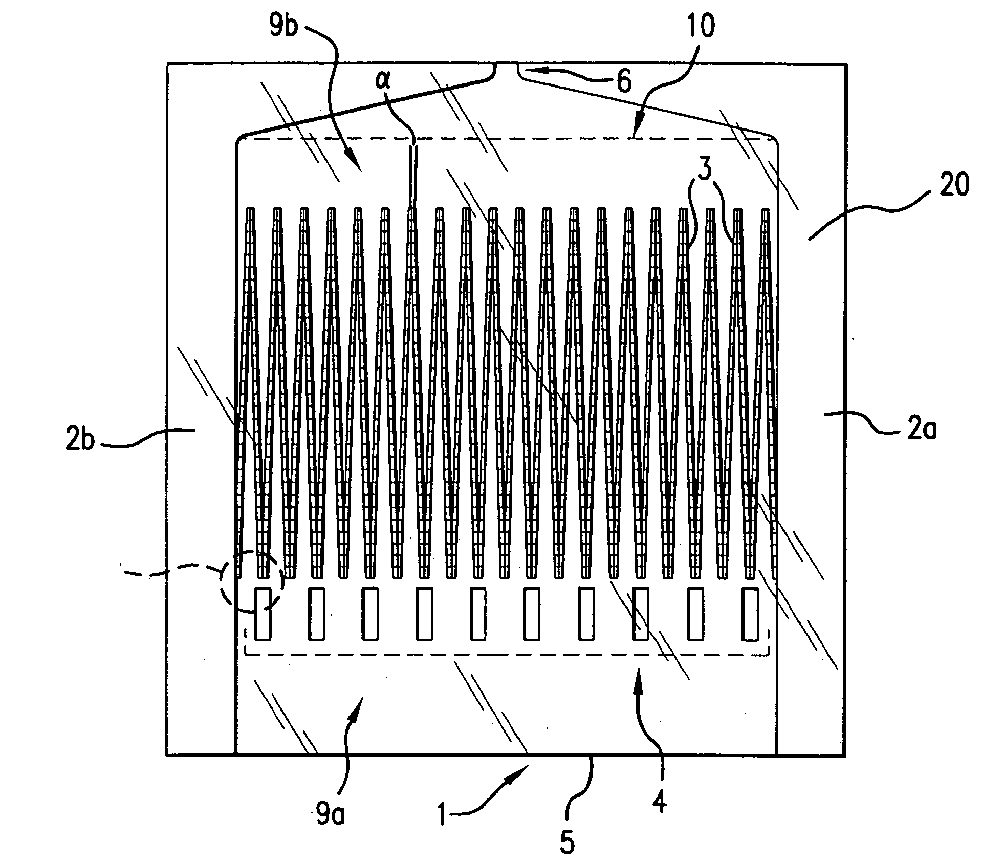
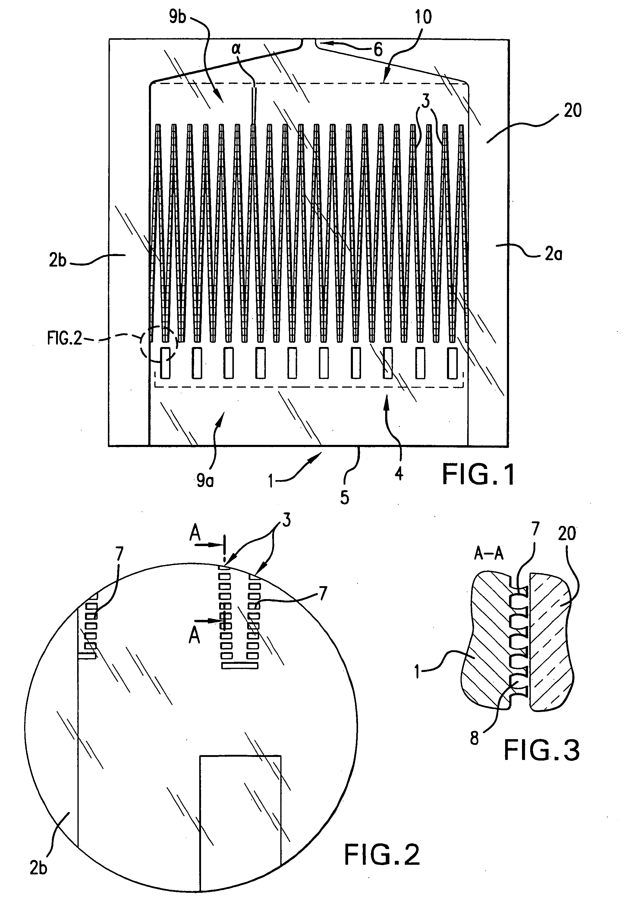
[0080] In this illustrative example, the filter is formed on a base plate together with a number of other microstuctured components. The base plate is 2.6 mm wide and about 5 mm long. On a width of about 2 mm it contains 40 rows of projections, with the rows arranged in a zig-zag configuration. Each row is 1.33 mm long. The projections are rectangular lands which are 10 .mu.m long and 2.5 .mu.m wide; and they project out of the base plate by 5 .mu.m. Provided between the lands are passages which are 5 .mu.m high and 3 .mu.m wide.

[0081] Disposed on the fluid entry side of the filter is a row of 10 rectangular lands which are 200 .mu.m long and 50 .mu.m wide; and they project out of the base plate by 10...


PUM

PropertyMeasurementUnit
Angleaaaaaaaaaa
Flow rateaaaaaaaaaa
Lengthaaaaaaaaaa

Abstract

A microstructured filter for a fluid, the filter having an inlet for unfiltered fluid and an outlet for filtered fluid, the filter comprising: a plurality of projections which are arranged in at least two rows in mutually juxtaposed relationship and which project out of a base plate and which are an integral component of the base plate, a plurality of passages between the projections and a cover plate which is securable to the base plate to cover the projections and the passages, wherein the passages form a plurality of through paths from the inlet to the outlet, said inlet comprises an elongate inlet slot for the unfiltered fluid, which extends over approximately the entire filter width and which is approximately as high as the projection projecting out of the base plate, on the outlet side of the filter. The filter according to the invention remains operational, even if a part of the filter area is obstructed. The filter is used for example in an atomizer with which an aerosol is produced from a fluid which contains a medicament.

Description

[0001] The present application is a continuation of, and claims the benefit under 35 U.S.C. .sctn. 120 of U.S. application Ser. No. 09 / 509,201, having a 35 U.S.C. .sctn. 371 date of Jun. 15, 2000, which was a National Phase application based on International Application No. PCT / GB98 / 02604, filed Aug. 28, 1998. The present application also claims the benefit under 35 U.S.C. .sctn. 119 of German patent application DE 197 42 439.2, having a filing date of Sep. 26, 1997. The disclosure of these referenced applications are incorporated by reference herein in their entirety.[0002] 1. Field of the Invention[0003] This invention relates to microstructured filters for fluids.[0004] 2. Background of the Invention[0005] Various filters are known, in which the filter medium has micropores down into the submicrometer range, the pore size being statistically distributed in dependence on the material. The external dimensions of filter media of this kind are powers of ten greater than the mean pore...

Claims


Application Information

Patent Timeline
IPC IPC(8): B01D29/44A61M15/00B01D29/03B01D39/16B01D39/20B01D46/12B01D46/52B01D67/00B01D71/02
CPCA61M11/00B01D2325/04A61M2205/0233B01D39/16B01D39/2003B01D39/2027B01D39/2068B01D46/0023B01D46/12B01D46/40B01D46/521B01D67/003B01D67/0058B01D67/0062B01D67/0069B01D71/022B01D2275/206B01D2325/021A61M15/00B05B15/40B01D46/62B01D29/03
Inventor KADEL, KLAUSGESER, JOHANNESEICHER, JOACHINFREUND, BERNHARDDUNNE, STEPHEN TERENCEBACHTLER, WULF
Owner BOEHRINGER INGELHEIM INT GMBH
Why Eureka
Try Eureka