Variable capacitors, composite materials

a capacitor and variable technology, applied in the field of variable capacitors, can solve the problems of affecting the charge carrier too quickly, the monoparticulate nature of the particulate may be lost, and the particular vulnerability of platinum particulates to being poisoned by carbon monoxide,

Inactive Publication Date: 2004-09-02
NGIMAT CO
View PDF3 Cites 20 Cited by
  • Summary
  • Abstract
  • Description
  • Claims
  • Application Information

AI Technical Summary

Problems solved by technology

If thin films are formed, the nanoparticulates may sinter together, e.g., at room temperature in the case of soft metals such as gold or with the application of heat to the substrate, whereby the monoparticulate nature of the particulates may be lost.
For example, platinum particulates are known to be useful as catalytic material in membranes of fuel cells, but platinum particulates are particularly susceptible to being poisoned by carbon monoxide.
While a significant number of charge carriers may be present in a material, if the mobility of those charge carriers is extremely low, the RF signal when applied to the capacitor plates, creates an electric field that changes too quickly to affect the charge carriers.
When these layers are thin, the chance of pin-hole defects (shorts) increases.
If too few charge carriers are present, the capacitance is not maximized and intermodulation distortions effects from increased RF power levels can dominate.
If too many charge carriers are present, then the bias voltage will only "freeze" a portion of the total available charge carriers.
Currently such thin tunable dielectrics are not used due to IMD and breakdown.

Method used


Image

  • Variable capacitors, composite materials
  • Variable capacitors, composite materials

Examples


embodiment 40

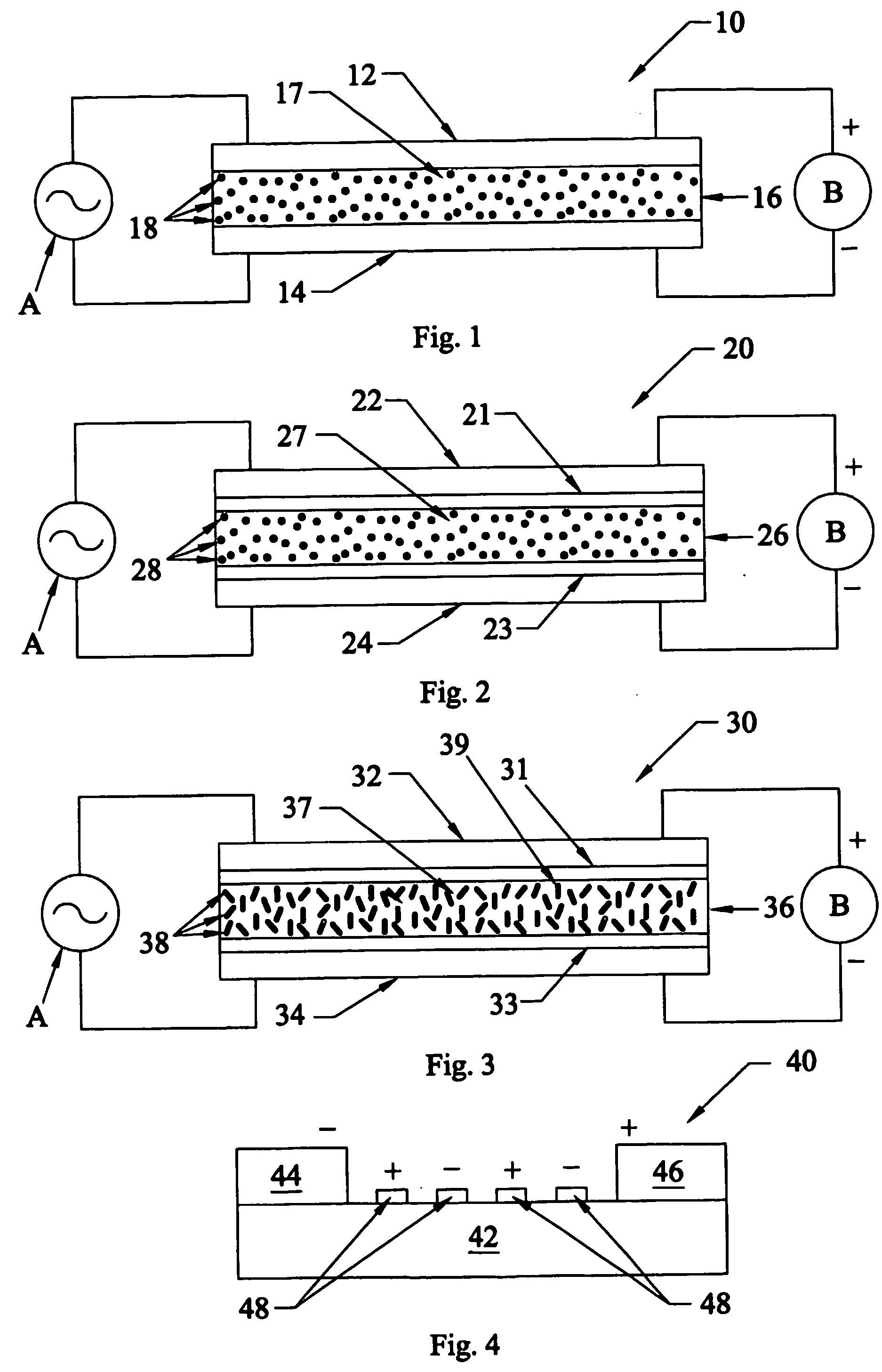
[0063] In FIG. 4, a further embodiment 40 of the capacitor of the present invention is shown. Capacitor 40 includes a dielectric material 42, having a first electrode 44, and a second electrode 46 on top of the dielectric 42. Between the electrodes 44 and 46 are a series of conductive strips 48 that interact with the RF field to increase the effective capacitance. Strips 48 may be electrically isolated, or may be connected (not shown) alternatively to a DC (or low frequency AC) biasing circuit for reasons described below. When a DC potential is applied to the electrodes 46 and 44 as shown by the + and - symbols, a DC voltage is induced in the strips 48 (also as shown by the + and - symbols). The symbols also represent the instantaneous biasing voltage that may be applied to strips 48, should they be connected to a biasing circuit.

[0064] Alternatively, strips 48 can be provided as a thin single layer between, but separate from, electrodes 44 and 46, to increase the dipoles strength. ...

example

[0071] A dielectric material layer, 0.345 microns thick comprising 33 mol % Pt and 66 mol % silica was deposited on a Pt-coated silicon substrate. Platinum particulates and silica were co-deposited from separate combustion chemical vapor deposition (CCVD) flames, such CCVD flame deposition being taught in U.S. Pat. No. 5,652,021. A second electrode layer made of silver was formed on the exposed surface of the dielectric layer. The capacitance in picofarads was measured at various biasing voltages. Results are as follows:

3 Biasing Voltage Capacitance 0 241.4 10 240.2 20 237.3 30 230.6 40 224.6


PUM

PropertyMeasurementUnit
biasing voltageaaaaaaaaaa
electron/hole mobilitiesaaaaaaaaaa

Abstract

Tunable capacitors (10, 20, 30, 40) have a dielectric material (16, 26, 36, 42) between electrodes, which dielectric material comprises an insulating material (17, 27, 37, 42) and electrically conductive material, (18, 28, 38, 48) e.g., conductive nanoparticulates, dispersed therein. In certain cases, enhanced tune-ability is achieved when the dielectric material comprises elongated nanoparticulates (38). Further enhanced tune-ability may be achieved by aligning elongated particulates in an electrode-to-electrode direction. Nanoparticulates may be produced by heating passivated nanoparticulates. Passivated nanoparticulates may be covalently bound within a polymeric matrix. High bias potential device structures can be formed with preferential mobilities.

Description

[0001] The present invention is directed to capacitors that can be tuned by a biasing voltage. The present invention is also directed to novel particulates and composite materials that are useful for forming tunable capacitors.[0002] One of the issues with variable capacitor materials, dielectrics--whose dielectric permittivities change when a electric bias is applied, is that these materials must be crystalline. These materials have a perovskite structure. Many of these tunable materials have higher losses than are desired, which lowers the performance of the functional devices.[0003] In addition, these materials have large temperature coefficients of capacitance. Therefore, it is hard to keep a constant capacitance without also knowing the temperature of the system. Monitoring and feedback loops are commonly required to compensate for changes in capacitance with temperature. Therefore, decreasing the effective overall change in capacitance can eliminate the need for a compensating...

Claims


Application Information

Patent Timeline
Patent Type & Authority Applications(United States)
IPC IPC(8): H01G4/06H01G7/06
CPCH01G7/06
Inventor HUNT, ANDREW TYEOLJACA, MIODRAGFLANAGAN, SCOTTDESHPANDE, GIRISHLEE, STEINFAGUY, PETER W.
Owner NGIMAT CO
Why Eureka
Try Eureka