Powder metal materials and parts and methods of making the same

Inactive Publication Date: 2004-09-16
KEYSTONE INVESTMENT CORP
View PDF21 Cites 59 Cited by
  • Summary
  • Abstract
  • Description
  • Claims
  • Application Information

AI Technical Summary

Problems solved by technology

This porosity is undesirable in certain applications as it creates areas of stress concentration during fatigue, which can result in premature fatigue failure.
Accordingly, it can be difficult to attain sufficient depth and uniformity of densification by surface rolling when the part to be densified has irregularly shaped surfaces.
Therefore, although surface rolling can be used to uniformly densify the surface of cylindrical P/M materials and parts, this method is less effective on irregularly shaped surfaces such as gear teeth, sprockets, and cams.
While it is possible to densify one or more core regions of the PM materials and parts using one of the aforementioned processes (for example DP/DS, HFA, or P/F) prior to surface rolling one or more surface regions of the part, because the P/M material is relatively "hard" after these processes, surface rolling is generally not as effective in incr

Method used


Image

  • Powder metal materials and parts and methods of making the same
  • Powder metal materials and parts and methods of making the same
  • Powder metal materials and parts and methods of making the same

Examples


example 1

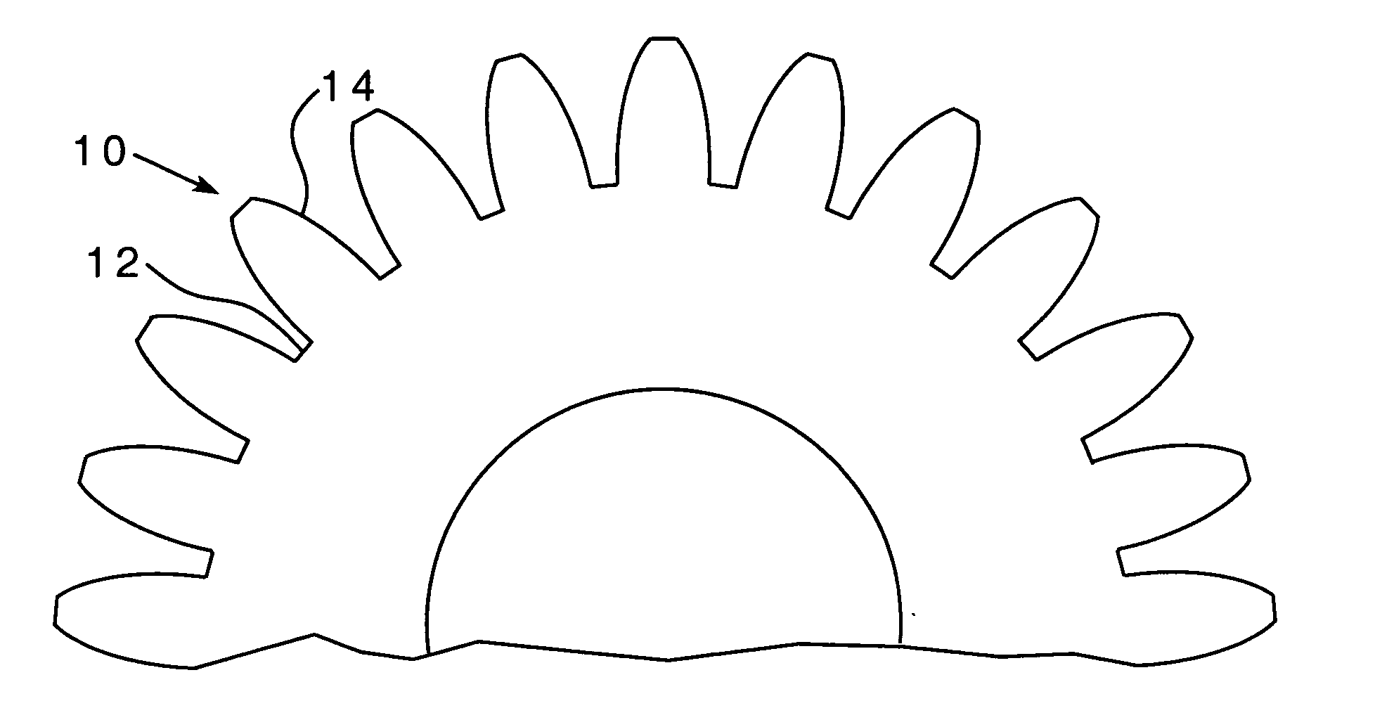
[0080] A gear was formed according to one non-limiting embodiment of the invention by compacting a powder metal composition comprising about 99.25 weight percent QMP 4401 and about 0.75 weight percent EBS wax lubricant at about 40 tsi to a density of 7.0 g / cc. The gear was then sintered at a temperature of about 2080.degree. F. for about 20 minutes. Thereafter, portions of the surface of the gear in the tooth root region and the tooth flank region were densified by shot peening. Shot peening involved impacting with SAE S70 shot (i.e., shot having a diameter ranging from about 0.016 to about 0.046 inches) for about 10 minutes at a pressure of 100 psi. After shot peening, the densified portions of the surface of the gear were uniformly densified to a density of 7.8 g / cc (which is about 99.1 percent of the theoretical density of the powder metal part) to a depth of 0.005 inches. Further, after shot peening, the part was sized at 55 tsi. After sizing, the core had a density of 7.5 g / cc ...

example 2

[0082] Three sets of 4600 steel-base spur gears (described below) were prepared by molding a powder compact to a green density of 6.8 g / cc and sintering at about 2080.degree. F. for about 20 minutes in a N.sub.2-10% H.sub.2 atmosphere. The same powder metal composition was used to form each set of parts.

[0083] The first set of parts (SET 1) was formed according to conventional means, except that the powder forging was controlled to achieve core density of 7.6 g / cc and a surface density of 7.55 g / cc as measured using image analysis.

[0084] The second set of parts (SET 2) was formed according to one non-limiting embodiment of the present invention by post-sinter shot peening portions of the surface of the part prior to powder forging, with all other process steps performed as described above. The shot peening process comprised impacting with SAE S70 shot (i.e., shot having a diameter ranging from about 0.016 to about 0.046 inches) for about 10 minutes at a pressure of 100 psi. After sh...

example 3

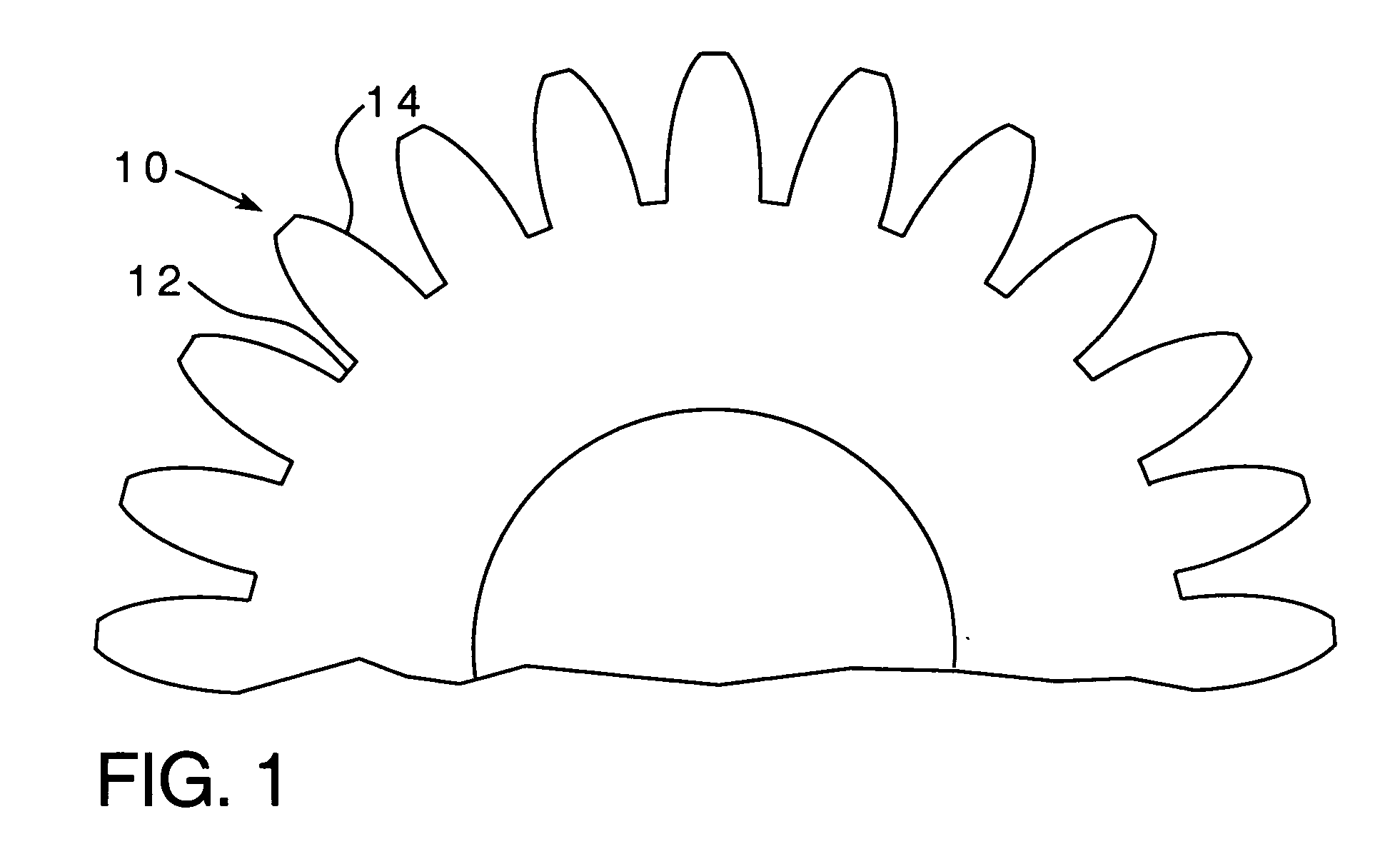
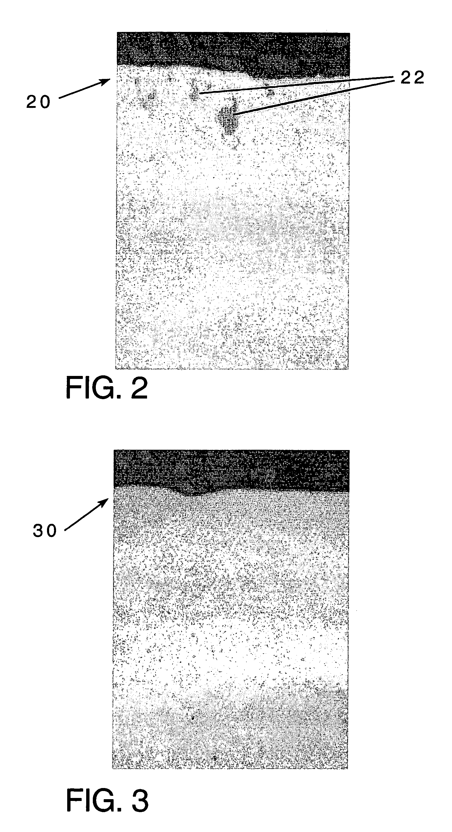
[0088] Two low carbon steel gears were formed by molding at 40 tsi and sintering at 2080.degree. F. for 20 minutes in a N.sub.2-10% H.sub.2 atmosphere. One gear was subsequently heated to 1800.degree. F. in a protective atmosphere and transferred to a die held at 600.degree. F. prior to powder forging at 60 tsi. As shown in FIG. 3, finger oxides 32 were present near the surface (generally indicated as 30) of the first gear after forging.

[0089] The second gear was processed under similar conditions to the first gear; however, portions of the surface of the second gear were shot peened as described above in Example 1 after sintering and prior to reheating and forging. As shown in FIG. 4, no finger oxides were present near the surface (generally indicated as 40) of the second gear after forging.


PUM

PropertyMeasurementUnit
Lengthaaaaaaaaaa
Lengthaaaaaaaaaa
Lengthaaaaaaaaaa

Abstract

Embodiments of the present invention relate to methods of forming powder metals materials and parts. More specifically, certain embodiments of the present invention relate to methods of forming powder metals materials and parts by densifying at least a portion of a surface of the materials and/or parts after sintering and prior to densifying one or more core regions of the materials and/or parts. Other embodiment provide powder metal parts, such as gears and sprockets, having surface regions that are uniformly densified to full density to depth ranging from 0.001 inches to 0.040 inches, and core regions that can have at least 92 percent theoretical density and further can have essentially full density, or full density. Still other embodiments relate to brazed, welded, plated and gas-tight powder metal parts and components that can be made in accordance with the various non-limiting methods disclosed herein.

Description

[0001] This application claims benefit of provisional application Serial No. 60 / 508,575, filed Oct. 3, 2003.[0002] Not applicable.REFERENCE TO A SEQUENCE LISTING[0003] Not applicable.[0004] Embodiments of the present invention relate to methods of forming powder metal materials and powder metal parts. More specifically, certain embodiments of the present invention relate to methods of forming powder metal materials and / or powder metal parts by densifying one or more surface regions of the materials and / or parts after sintering and prior to densifying one or more core regions of the materials and / or parts. Other embodiments provide powder metal parts, such as gears and sprockets, having surface regions and core regions having essentially full density. Still other embodiments related to brazed, welded, plated and gas-tight powder metal parts and components that can be made in accordance with the various non-limiting methods disclosed herein.[0005] The mechanical properties of powder m...

Claims


Application Information

Patent Timeline
IPC IPC(8): B22F3/16
CPCB22F3/164B22F2003/241B22F2998/00B22F2998/10B22F5/08B22F7/004B22F3/10B22F2003/166B22F3/17B22F3/24
Inventor KOSCO, JOHN C.
Owner KEYSTONE INVESTMENT CORP
Why Eureka
Try Eureka