Rock-bolting apparatus and method

a boom arm and rock technology, applied in shaft equipment, shaft lining, drilling pipes, etc., can solve the problems of fracturing solid rock, rock fracture beyond the desired geometric shape of the tunnel cross-section, tunnel roof or back and/or drive side walls to be unstable, etc., to achieve a longer stroke and a shorter stroke

Inactive Publication Date: 2004-09-16
RME UNDERGROUND
View PDF12 Cites 31 Cited by
  • Summary
  • Abstract
  • Description
  • Claims
  • Application Information

AI Technical Summary

Benefits of technology

0017] Preferably said pair of links can be manipulated between said extremities to provide multiple modes of operation, to provide a longer stroke for blast hole drilling and a shorter stroke for drilling and bolting.

Problems solved by technology

In the blasting stage the explosive is detonated, the resulting blast fracturing the solid rock.
An unavoidable consequence of this proven method is rock fracture beyond the desired geometric shape of the tunnel cross-section.
This rock fracturing can cause the tunnel roof or back and / or the drive's side-walls to be unstable.
Falling particles larger than a tennis ball can prove fatal to personnel.
These bolts rust away in time and jeopardize long-term security.
These bolts also rust away in time and jeopardize long-term security.
The multi-axis support arm, while capable of supporting the mechanism, tends to deflect, has low natural frequencies of bobbing up / down and back / forth and also has poor `fine control`.
In use, problems arise because of the physical properties of the freshly fractured rock surface.
When the blunt drill head strikes an angled rock face in attempting to collar a new hole, it generally cannot achieve penetration.
The drill bit, sliding down the rock face and into the `valley` demands lateral compliance since the support arm's hydraulics have not yielded or adjusted.
The bolt has little chance of finding the hole because the mechanical `slop` (play, clearance, backlash) is endemic, with machine parts which are expected to operate reliably despite spending their lives in a shower of water, grit and falling rocks.
Attempting to insert an all metal bolt is normally unsuccessful.
This is the most dangerous time with a high risk of falling rock causing death or injury.
With epoxy-grouted bolts, these aiming problems can see the two-part epoxy sausage bursting, covering the drilled / bolting mechanism and / or the hole opening with rapidly setting epoxy, which can disable the mechanism and / or block the hole.

Method used


Image

  • Rock-bolting apparatus and method
  • Rock-bolting apparatus and method
  • Rock-bolting apparatus and method

Examples


Embodiment Construction

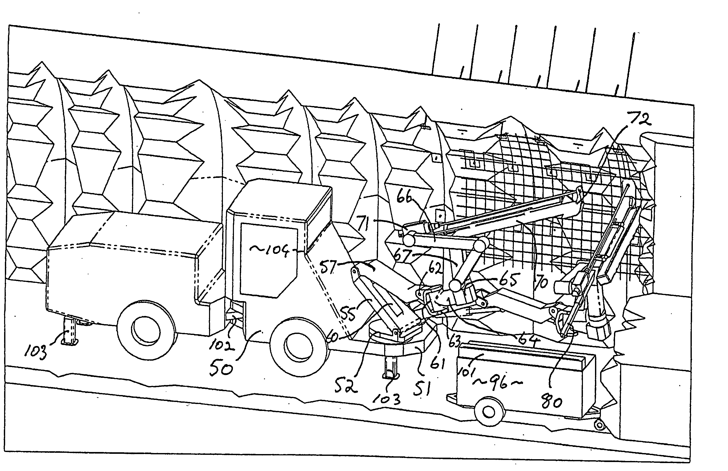
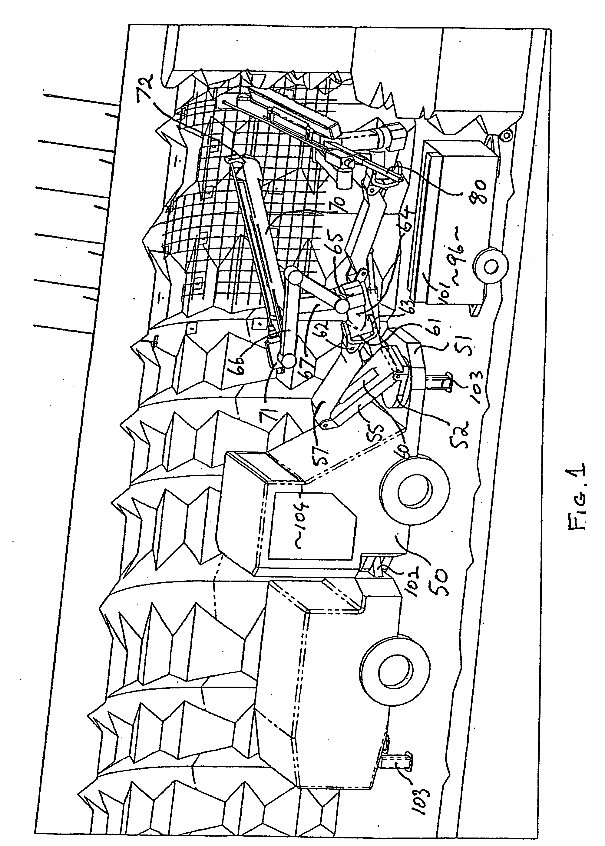
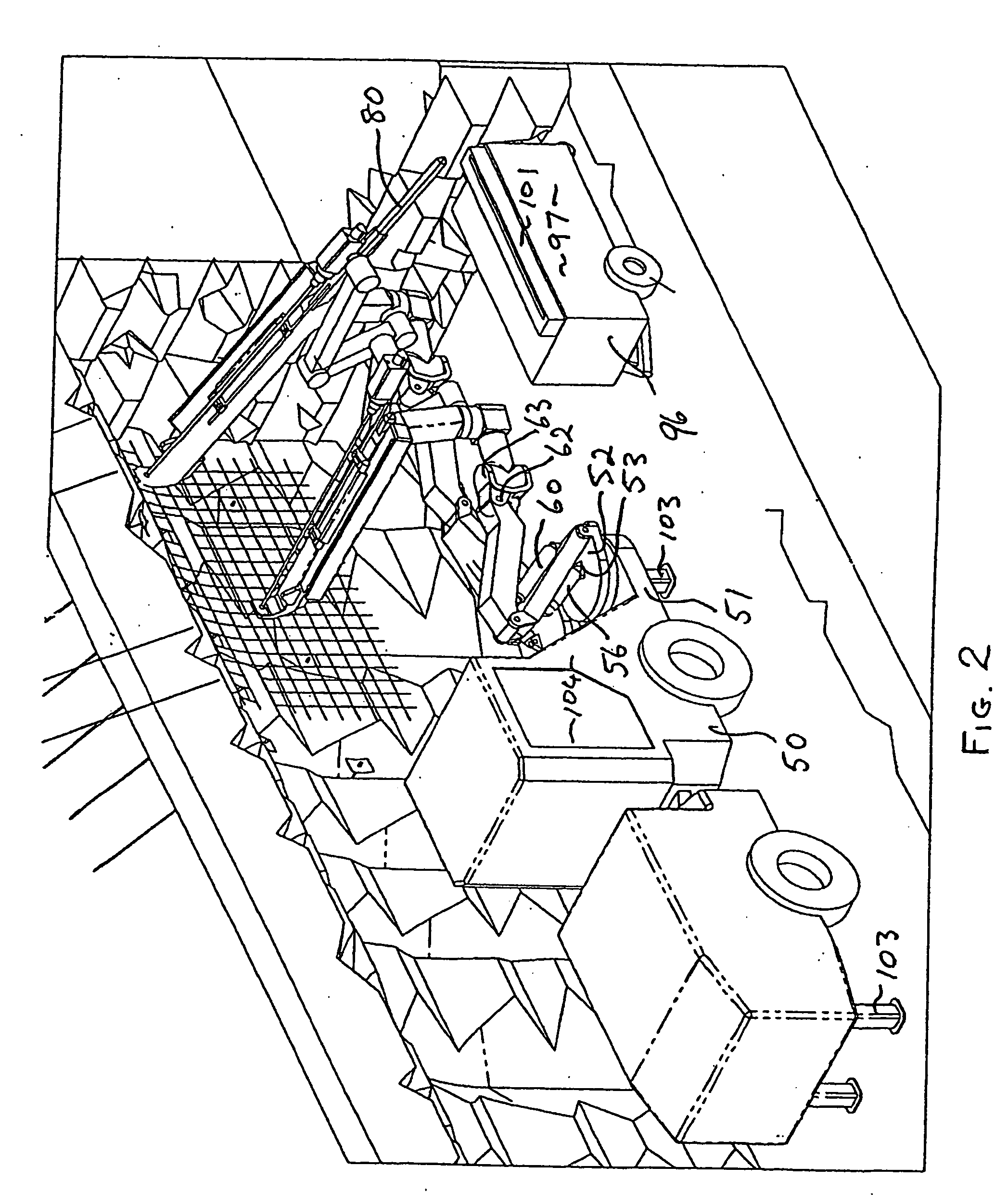
[0051] In the embodiment illustrated in FIGS. 1 to 15, there is shown a rock bolting apparatus in accordance with the present invention having a twin-boom jumbo chassis forming carriage 50. Machinery platform 51 of carriage 50 mounts a pair of slewing bases 52. The slewing bases 52 each have a pair of spaced hard points 54 for pivotally mounting a primary arm lower member 55, the relative disposition of which is provided by a ram 56 disposed between lower member 55 and a third hard point 53 on slewing base 52. A primary arm upper member 57 is hinged to lower member 55, and the relative disposition of the upper member 57 and lower 55 members is controlled by a ram 60 disposed between the upper and lower arms.

[0052] The upper and lower arms operate in a vertical plane that can be slewed via the slewing base. A yoke 61 is pivoted to the outer end of the upper member 57 via a yoke pivot 62 having an axis substantially parallel to the articulation between the upper and lower members. The...


PUM


Abstract

An articulated boom arm for a rock boring machine, comprising a first kinked member having a drill guide at one end and a base pivot at the other end, and a pair of pivoted links. One of said links having a first end pivoted at said base pivot, the other of the links having a drill pivotally mounted at a first end thereof. The second ends of The first and second links being pivoted to each other whereby said drill is reciprocally linearly movable along said first member with a drill bit aligned with said drill guide and at one extremity of the reciprocal movement both said pair of links are substantially longitudinally aligned and extend towards said drill guide, and at the other extremity of the reciprocal movement both said pair of links are substantially longitudinally aligned and extend away from said drill guide.

Description

[0001] This invention relates to a rock-bolting apparatus and method.[0002] This invention has particular but not exclusive application to a rock-bolting apparatus and method for use in mine construction, and for illustrative purposes reference will be made to such application. However, it is to be understood that this invention could be used in other applications, such as general tunnel construction, underpinning and the like.[0003] Underground mining of mineral ores, such as coal and hard and soft rock mining requires the `development` of underground drives in the form of tunnels. In all hard-rock applications, drive development is achieved through a drilling, charging, blasting, and mucking cycle. In the drilling stage of the cycle, a pattern of holes is drilled into the blind end of the drive. The holes are generally parallel to the drive axis. Typically, holes are 2-4 metres deep.[0004] In the charging stage, explosive is placed in the drilled holes and connected via a detonati...

Claims


Application Information

Patent Timeline
Patent Type & Authority Applications(United States)
IPC IPC(8): E21B19/087E21D11/15E21D11/40E21D20/00
CPCE21B19/087E21D20/006E21D11/40E21D11/152
Inventor RUBIE, PETER JOHNRUSSELL, ALAN JOHN
Owner RME UNDERGROUND
Why Eureka
Try Eureka