Radio communication apparatus, radio communication method, antenna apparatus and first duplexer

a radio communication device and antenna technology, applied in the direction of volume compression/expansion, polarised antenna unit combinations, electromagnetic wave modulation, etc., can solve the problems of deteriorating reception, accelerating the pace of deterioration of reception, and consequently deteriorating reception

Inactive Publication Date: 2004-09-16
PANASONIC CORP
View PDF14 Cites 61 Cited by
  • Summary
  • Abstract
  • Description
  • Claims
  • Application Information

AI Technical Summary

Problems solved by technology

In the case where its own transmitting signal leak not completely attenuated by the duplexer is inputted to the low-noise amplifier, the following three factors cause deterioration of reception respectively.
It is caused because current noise increases due to increase in currents of the low-noise amplifier caused by a transmitting signal leak, or high-frequency thermal noise is down-converted in the receiving band or inversely low-frequency thermal noise is up-converted in the receiving band due to the transmitting signal leak.
Secondly, it is because of gain compression of the low-noise amplifier due to the transmitting signal leak of the large amount of power. FIG. 33 shows a relationship between the transmitting signal leak level and the gain.
If the gain of the low-noise amplifier is reduced by the transmitting signal leak, however, the influence of the noise characteristic of the circuit in the subsequent stage becomes significant so that the reception is consequently deteriorated.
Thirdly, it is because of intermodulation due to the transmitting signal leak of the large amount of power.
For this reason, if there is a narrow-band jammer of an analog cellular system using a near band of a CDMA cellular system in the proximity of a wave desired to be received for instance, the a

Method used


Image

  • Radio communication apparatus, radio communication method, antenna apparatus and first duplexer
  • Radio communication apparatus, radio communication method, antenna apparatus and first duplexer
  • Radio communication apparatus, radio communication method, antenna apparatus and first duplexer

Examples


first embodiment

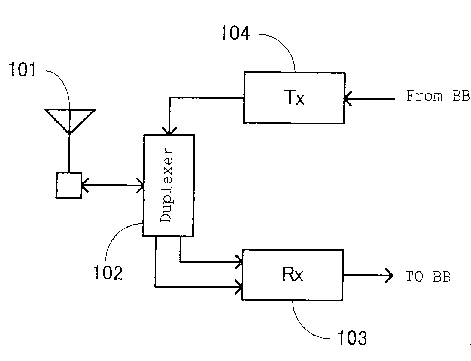
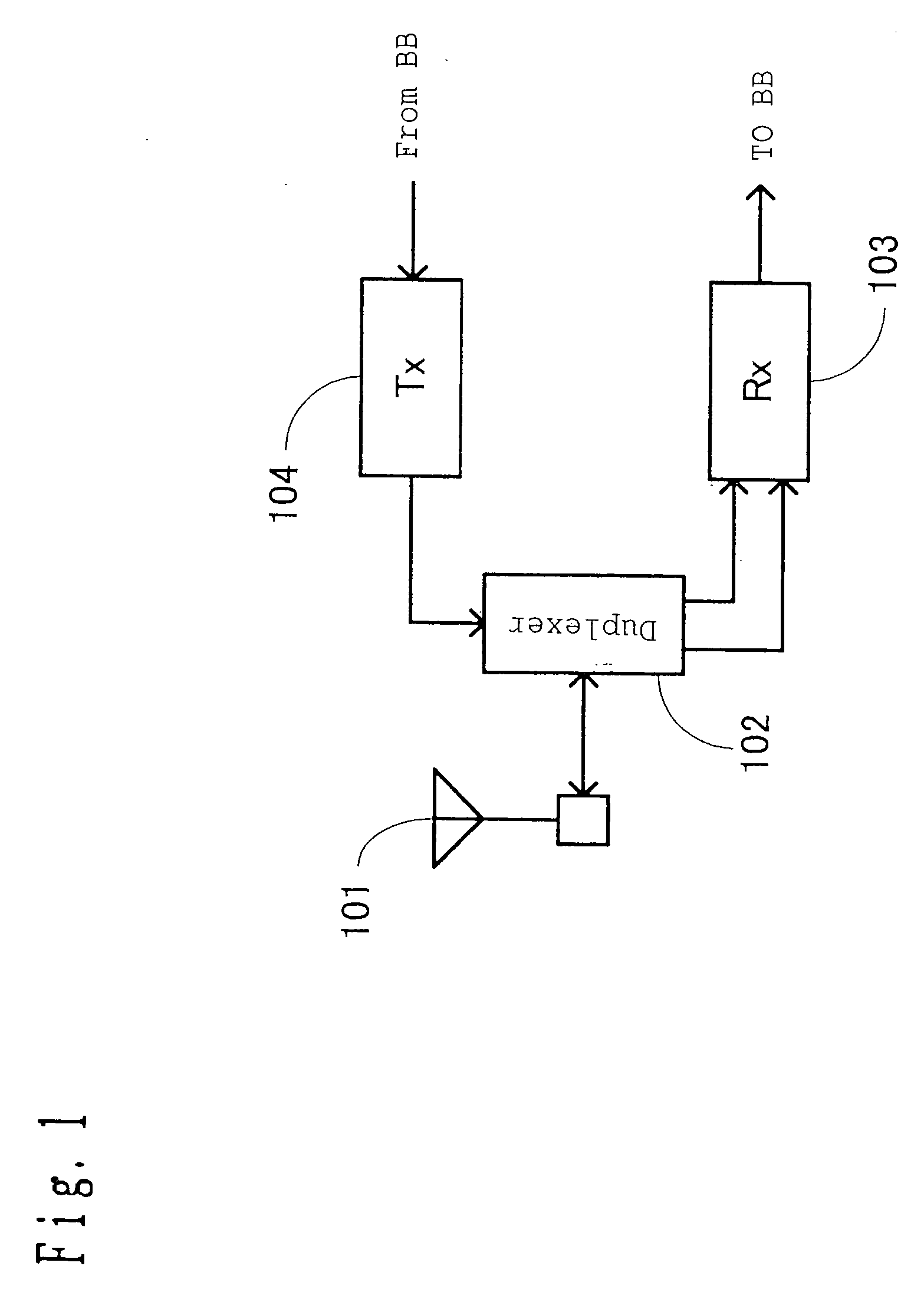
[0163] FIG. 1 is a circuit diagram of a radio communication apparatus related to a first embodiment of the present invention. In this diagram, reference numeral 101 denotes a single-phase input-output antenna corresponding to a first antenna of the present invention as an example, 102 denotes a duplexer (antenna sharing apparatus) of which transmission input terminal is a single-phase input type, antenna input-output terminal is a single-phase input-output type, and receiving output terminal is a balanced output type as an example of a first duplexer of the present invention, 103 denotes a receiving circuit of differential input as an example of a first receiving apparatus of the present invention, and 104 denotes a single-phase output transmitting circuit as an example of a first transmitting apparatus of the present invention. The duplexer 102 outputs a signal in a frequency band (corresponding to a second frequency band of the present invention) of the receiving signal inputted f...

second embodiment

[0195] FIG. 11 is a circuit diagram of the radio communication apparatus related to a second embodiment of the present invention. In FIG. 11, the same components as those shown in FIG. 1 are given the same symbols, and a description thereof will be omitted. In FIG. 11, reference numeral 902 denotes a duplexer of which terminals are single-phase input-output, and 905 denotes a phase shifter of single-phase input and balanced output which outputs the signals in the frequency band of the receiving signals as the differential signals and outputs the signals in the frequency band of the transmitting signals as the in-phase signals. Here, the first duplexer of the present invention is corresponding as an example to the duplexer 902 and the phase shifter 905.

[0196] As for the radio communication apparatus shown in FIG. 11, the radio frequency signal transmitted from the base station is received by the antenna 101 as in FIG. 1 and is then inputted to the receiving circuit 103 via the duplex...

third embodiment

[0208] FIG. 13 is a circuit diagram of the radio communication apparatus related to a third embodiment of the present invention. In FIG. 13, the same components as those shown in FIG. 1 are given the same symbols, and a description thereof will be omitted. In FIG. 13, an antenna 1101+ and an antenna 1101- are examples of second and third antennas of the present invention, and a duplexer 1102 is an example of a second duplexer of the present invention comprising separate terminals, that is, the transmission input terminal is the single-phase input type, the receiving output terminal is the balanced output type, and the antenna input-output terminal is the balanced input-output type.

[0209] As for the radio communication apparatus shown in FIG. 13, the radio frequency signal transmitted from the base station is received by the antennas 1101+ and 1101- as in FIG. 1 and is then inputted to the duplexer 1102. Furthermore, the signal outputted from the duplexer 1102 is inputted to the rece...


PUM


Abstract

The radio communication apparatus comprising an antenna, a transmitting circuit of outputting a transmitting signal in a first frequency band, a duplexer, connected to the antenna and having a single-phase input terminal and a balanced output terminal, of conveying the transmitting signal inputted to the single-phase input terminal to the antenna and outputting a receiving signal in a second frequency band different from the first frequency band received from the antenna substantially as a differential signal from the balanced output terminal, and a receiving circuit connected to the balanced output terminal and having a circuit in which a gain of a signal of a differential component is higher than that of a signal of an in-phase component, or a loss of the signal of the differential component is lower than that of the signal of the in-phase component.

Description

[0001] 1. Field of the Invention[0002] The present invention relates to a field of simultaneous transmission and reception of a signal in a communication system having a transmitter and a receiver such as a portable telephone, and in particular, to a radio communication apparatus in the communication system using a modulation method having an envelope component such as a CDMA method.[0003] 2. Related Art of the Invention[0004] In recent years, a cellular radio communication system is spreading rapidly due to increasing needs for mobile communication and development of communication technology.[0005] A radio communication apparatus used in the cellular radio communication system is constituted as shown in a block diagram in FIG. 31 for instance. In this drawing, reference numeral 1801 denotes an antenna, 1802 denotes a duplexer (antenna sharing apparatus), 1803 denotes a receiving circuit, and 1804 denotes a transmitting circuit.[0006] In the radio communication apparatus shown in FI...

Claims


Application Information

Patent Timeline
IPC IPC(8): H04B1/56H01P1/213H01P5/10H01Q13/08H01Q21/24H03G7/00H03G9/28H04B1/3822H04B1/52
CPCH04B1/525H04B1/56
Inventor NAKATANI, TOSHIFUMIYAMAMOTO, ATSUSHIADACHI, HISASHI
Owner PANASONIC CORP
Why Eureka
Try Eureka