All-Digital Phase Modulator/Demodulator Using Multi-Phase Clocks and Digital PLL

a digital phase modulator and all-digital technology, applied in the field of electronic signal transmission, can solve the problem that analog components are difficult to integrate with large digital system chips

Active Publication Date: 2004-10-07
KINGSTON DIGITAL CO LTD
View PDF35 Cites 15 Cited by
  • Summary
  • Abstract
  • Description
  • Claims
  • Application Information

AI Technical Summary

Problems solved by technology

However, these analog components are difficult to integrate with large digital system chips.

Method used


Image

  • All-Digital Phase Modulator/Demodulator Using Multi-Phase Clocks and Digital PLL
  • All-Digital Phase Modulator/Demodulator Using Multi-Phase Clocks and Digital PLL
  • All-Digital Phase Modulator/Demodulator Using Multi-Phase Clocks and Digital PLL

Examples


Embodiment Construction

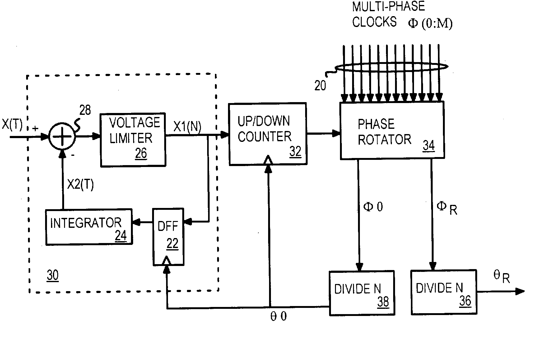
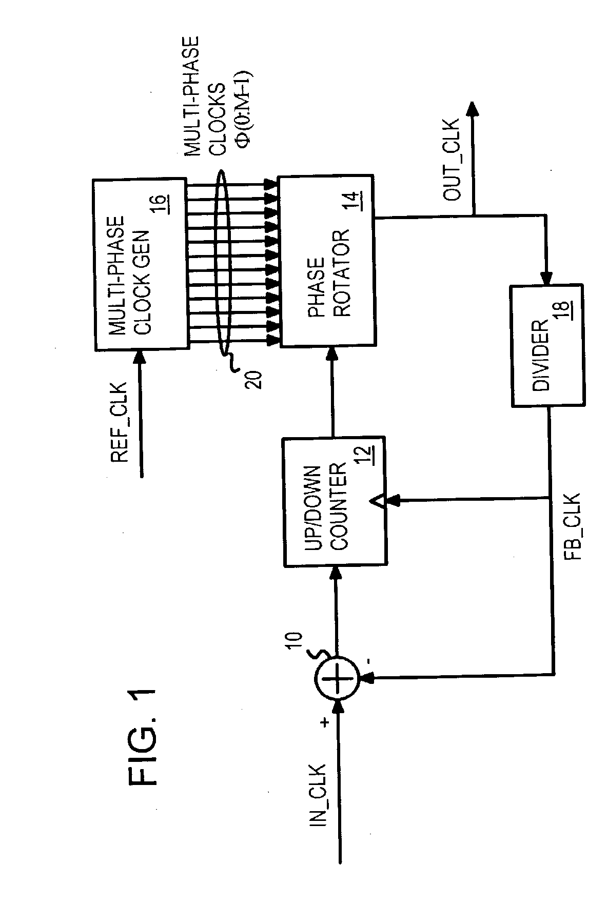
[0057] Several other embodiments are contemplated by the inventor. For example additional components may be added, and inversions or active-low signals may be used. Banks of phase rotators may be used. A nested counter and nested phase rotators may be used to select the multi-phase clock in a multi-level scheme. Various filtering can be added, such as to smooth the loop responses. Rather than use the first multi-phase clock .PHI.0 for feedback, other multi-phase clocks could be selected as the fixed clock. The feedback and output dividers could use different divisors N, P rather than the same divisor. The multi-phase clocks could be a subset of the possible phases, such as by skipping every other phase, or only using one-quarter of the possible phases.

[0058] Voltage limiter 26 can be combined with comparator 28 in some implementations. The voltage limiter can be voltage comparator. A voltage summing or difference circuit could also be used. The integrator could also be a capacitor w...


PUM


Abstract

Multi-phase clocks are used to encode and decode signals that are phase- modulated. The input signal is phase-compared with a feedback clock. Phase differences increment or decrement an up/down counter. The count value from the up/down counter is applied to a phase rotator, which selects one clock phase from a bank of multi-phase clocks. The multi-phase clocks have the same frequency, but are offset in phase from each other. An output divider divides the selected multi-phase clock to generate a phase-modulated output. A feedback divider divides a fixed- phase clock from the multi-phase clocks to generate the feedback clock. An analog or a digital front-end may be used to convert analog inputs to digital signals to increment or decrement the counter, or to encode multiple digital bits as phase assignments. For a de-modulator, a digital-to-analog converter (DAC) or a digital decoder produces the final output from the count of the up/down counter.

Description

BACKGROUND OF INVENTION[0001] This invention relates to electronic signal transmission, and more particularly to using all-digital Phase-locked loops (PLL's) in modulators and demodulators.[0002] Digital implementations of phase-locked loops (PLL's) are widely used in various applications, such as digital communications and clock / data recovery. Conventional implementations of digital phase-locked loops normally use a numerically controlled oscillator (NCO) as the frequency source. An NCO (also known as a digitally controlled oscillator or DCO), particularly one implemented as counter, suffers from phase resolution or frequency granularity at high frequency.[0003] Another type of digital PLL uses a set of multi-phase clocks rather than a variable-frequency oscillator. Using Multi-phase clocks can improve the phase resolution of digitally implemented oscillators. Phase resolution is improved by sequentially selecting a phase (in ascending and descending order) from the multiphase cloc...

Claims


Application Information

Patent Timeline
Patent Type & Authority Applications(United States)
IPC IPC(8): H03C3/09H03L7/081H04L27/22
CPCH03C3/0966H03L7/0814H03L2207/50H04L27/22
Inventor CO, RAMON S.
Owner KINGSTON DIGITAL CO LTD
Why Eureka
Try Eureka