Radiographic inspection apparatus and radiographic inspection method

a radiographic inspection and inspection apparatus technology, applied in the direction of instruments, diaphragms/collimeters, diaphragms for radiation diagnostics, etc., can solve the problem that the detection sensitivity of .gamma rays cannot be enhanced in the radiation d

Inactive Publication Date: 2004-10-14
HITACHI LTD
View PDF8 Cites 12 Cited by
  • Summary
  • Abstract
  • Description
  • Claims
  • Application Information

AI Technical Summary

Problems solved by technology

ctors. However, even with the use of such a collimator, the detection sensitivity of .gamma. rays cannot be enhanced in the radiation det

Method used


Image

  • Radiographic inspection apparatus and radiographic inspection method
  • Radiographic inspection apparatus and radiographic inspection method
  • Radiographic inspection apparatus and radiographic inspection method

Examples


embodiment 1

[0042] (Embodiment 1)

[0043] Explanation will be made of an radiographic inspection apparatus in a preferred embodiment of the present invention with reference to FIGS. 4 and 5.

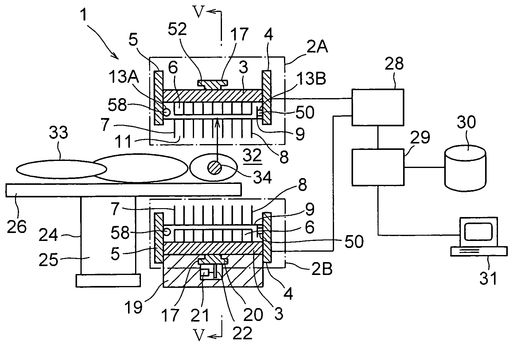
[0044] The radiographic inspection apparatus 1 in this embodiment is composed of radiation detecting devices 2A, 2B, a device 24 for supporting a person to be examined, a signal processing device 28 and a tomogram forming device 29. Since the radiation detecting devices 2A, 2B have the same structure, explanation will be made of the structure of the radiation detecting devices as to the radiation detecting device 2A. The radiation detecting device 2A incorporates in its casing (indicated by the one-dot chain line) several radiation detectors 6, a collimator device 7 and collimator displacement device 13A, 13B. The support device 24 for a person to be examined has a support member 25 and a bed 26 located at the top end of the support member 25, being set on the support member 25 so as to be movable in the longi...

embodiment 2

[0079] (Embodiment 2)

[0080] Explanation will be hereinbelow made of an embodiment 2 of the present invention. The radiographic inspection apparatus in this embodiment has the same configuration as that of the radiographic inspection apparatus 1 as stated above, except that the motor moving device for moving the motor for rotating the pinion 45, and the motor moving device 51 are eliminated from the radiation detecting devices 2A, 2B. Thus, in the radiographic inspection apparatus in this embodiment, the rack 12A and the pinion 45 and further the rack 12A and the pinion 47 are always meshed with each other. When the collimator devices are displaced in the direction of the arrow 53, the rack 12B slides between teeth of the pinion 47 while when the collimator devices are displaced in the direction of the arrow 54, the rack 12A slides between the teeth of the pinion 45. The motor 58 and the motor 50 are laid on the collimator holding members 4, 5.

[0081] In this embodiment, the advantage...

embodiment 3

[0083] (Embodiment 3)

[0084] Explanation will be hereinbelow made of a radiographic inspection apparatus in a third embodiment with reference to FIGS. 9 and 10. The radiographic inspection apparatus in this embodiment has the same configuration as that of the radiographic inspection apparatus in the embodiment 1, except that radiation detecting device 2C, 2D are used instead of the radiation detecting devices 2A, 2B. The radiation detecting devices 2C has the same configuration as that of the radiation detecting device 2D, only the radiation detecting device 2C will be explained.

[0085] The radiation detecting device 2C incorporates, within a casing (which indicated by a one-dot chain line), several radiation detectors 6, a collimator device 7 and a collimator moving device 13C. The configuration of the radiation detecting device 2C is the same as that of the radiation detecting device 2A, except the collimator device 7A and the collimator moving device 13C. The collimator device 7A i...


PUM


Abstract

In a radiographic inspection device which can shorten the inspection time and which can enhance the spatial resolution of thus obtained image, has two first and second radiation detecting devices each of which comprises several radiation detectors, a collimator device and a collimator moving device. The collimator device incorporates grid-like shield members defining several gamma ray passages. Each of the gamma ray passages has a cross-sectional area which is greater than that of each of the radiation detectors. The collimator device in the first radiation detecting device is moved in the longitudinal direction through the rotation of a motor in the collimator moving device while the collimator device in the second radiation detecting device is moved in a direction orthogonal to the longitudinal direction through a motor in the collimator moving device. Since the cross-sectional area of the gamma ray passage is greater than that of the radiation detector, the sensitivity of detection of gamma rays as to the radiation detector is enhanced, thereby it is possible to greatly shorten the inspection time. Further, since the collimator devices are moved by the collimator moving devices, respectively, the spatial resolution by the tomogram can be enhance.

Description

[0001] The present invention relates to a radiographic inspection apparatus and a radiographic inspection method, and in particular to a radiographic inspection apparatus and a radiographic inspection method which are preferably applied for a single photon emission computed tomography (which will be hereinbelow referred to as "SPECT") and a digital radiography.[0002] Inspections using radioactive rays have been used in a technology in which a function or a configuration in the human body of a person to be examined as an object to be tested is non-invasively imaged. Among then, there has been used, as a typical inspection method, the SPECT or the digital radiography using an ionizing radiation which can cause ionization.[0003] The SPECT doses a radiopharmaceutical containing a single photon emission nuclide (.sup.99Tc, .sup.67Ga, .sup.201Ta or the like) as a radionuclide and a substance having such a behavior that it accumulates to a specific neoplasm (cancer) or a specific molecule,...

Claims


Application Information

Patent Timeline
Patent Type & Authority Applications(United States)
IPC IPC(8): G21K1/02A61B6/06G01T1/00G01T1/161G01T1/164G01T7/00
CPCG01T1/1644A61B6/4258A61B6/037
Inventor UMEGAKI, KIKUOKOJIMA, SHINICHIUENO, YUUICHIROUAMEMIYA, KENSUKEYANAGITA, NORIHITOKITAGUCHI, HIROSHITSUCHIYA, KATSUTOSHIYOKOI, KAZUMA
Owner HITACHI LTD
Why Eureka
Try Eureka