
Method and device for manufacturing tubular packs filled with a material as well as tubular pack filled with a material

a technology of tubular packs and materials, applied in the direction of containers, tray containers, applications, etc., can solve the problems of difficult recycling, limited preservation of tubular packs, and often tightness problems

Inactive Publication Date: 2004-10-28
FRANS VERMEE
View PDF2 Cites 2 Cited by
  • Summary
  • Abstract
  • Description
  • Claims
  • Application Information

AI Technical Summary

Benefits of technology

[0011] In the method for manufacturing tubular packs filled with a material according to the invention, a tube filled with the material is initially wound with an embracing means in at least two displacement areas. The winding of the tube with the embracing means is effected over at least an entire circumference so that a winding angle of more than 360.degree. is formed. Through the area within the displacement area in which the embracing means is arranged, a winding area is defined. Since the holding force of the embracing means strongly increases with the winding angle, the strength of the winding in the displacement or winding area of the tube can be increased by a correspondingly high number of embracings whereby the tightness is improved. The embracing means is further fixed in the displacement area so that the embracing means is not able to unwind so that the tubular pack is tightly sealed. The embracing means is particularly fixed in the winding area. Thus, a particularly tight sealing of the tubular pack is created by winding, which remains tight, too, by fixing.
[0012] Since the tubular pack filled with the material can be strongly constricted by the method according to the invention, the tightness of the tubular pack is clearly increased. Thereby, the stock keeping can be improved since it can possibly be done totally without cooling. Particularly With foodstuff, the increased tightness results in that the preservability is increased. Further, the method according to the invention can be employed in an extremely variable manner since tubular packs with extremely different diameters can be processed.
[0013] The embracing means may have a cord-like configuration so that the length of the embracing means can be individually adapted, particularly automatically, in dependence on the application. As tubular envelope, a great variety of materials with a great variety of material thicknesses can be particularly used since the material used can always be automatically gathered into the state of maximum or desired tightness. Irregular surfaces or material bulgings or the like hardly have any influence upon the tightness of the tubular pack. Particularly if the embracing means consists of a material similar to that of the tube used, the recycling of the tubular pack manufactured according to the method according to the invention can be clearly simplified since the material to be utilized is largely of the same kind. With a cord-shaped embracing means, the displacement area in which there is substantially no material can be kept relatively narrow in comparison with the use of metallic sealing clamps. Further, it is possible to seal two ends of two different tubular packs with a single embracing means. In contrast to the use of two metallic sealing clamps in the area of displacement, one operational step is saved whereby the manufacture of tubular packs can be effected more rapidly. Thereby, the method according to the invention is particularly suitable for the mass production.
[0014] It is particularly provided that substantially no material is left in the displacement area so that the tubular pack is sealed as tightly as possible. This can be achieved by additionally displacing the material in the displacement area prior to winding the tube, e.g., by means of a squeezing means that squeezes the product to be packed out of the displacement area. In this case, the displacement area may be clearly larger than the winding area. Instead, however, it is also possible to achieve the displacement of the material in the tube by the winding itself. In this case, the displacement area is substantially as large as the winding area or slightly larger. This can be implemented by the fact that the embracing, means is under the effect of a tensile force during winding. While the embracing means is wound around the tube filled with the material, a radially acting force is applied onto the surface of the tube because of the tensile force in the embracing means. Thereby, the material is laterally pressed out of the displacement area in a manner similar to squeezing. A combination of the two steps is also possible, e.g., by partially displacing the material in the tube by means of a squeezing tool and then performing the winding in that area, whereby the remaining material is simultaneously displaced. By this measure, it can be prevented that inadvertently, the tube filled with the material is unintentionally separated or damaged by the shearing forces produced during winding.

Problems solved by technology

Such sealing clamps have the disadvantage that tightness problems often occur, particularly because of the overlapping ends of the sealing clamps.
This leads to that the preservability of such products is limited and the products have to be stored in cold storage shelves.
Further, the combination of a metallic sealing clamp with a plastic tubular pack makes the recycling more difficult-since the material to be utilized is not of the same kind.
Another disadvantage consists in that only sealing clamps of a certain size can be processed by the device described.
The processable dimensional tolerances are extremely small.
Further, a processing of different packaging materials is difficult if they have different material thicknesses and, as a consequence, in the gathered state, a different amount of material occurs at that location where the sealing clamp is arranged.
Particularly with tubular packs with a small material thickness, this very often results in tightness problems since non-sealed cross-sectional surfaces are created.
To be able to process different tubular packs with this device, very troublesome modifications are required.
Thus, a particularly tight sealing of the tubular pack is created by winding, which remains tight, too, by fixing.

Method used


Image

  • Method and device for manufacturing tubular packs filled with a material as well as tubular pack filled with a material
  • Method and device for manufacturing tubular packs filled with a material as well as tubular pack filled with a material
  • Method and device for manufacturing tubular packs filled with a material as well as tubular pack filled with a material

Examples


Embodiment Construction

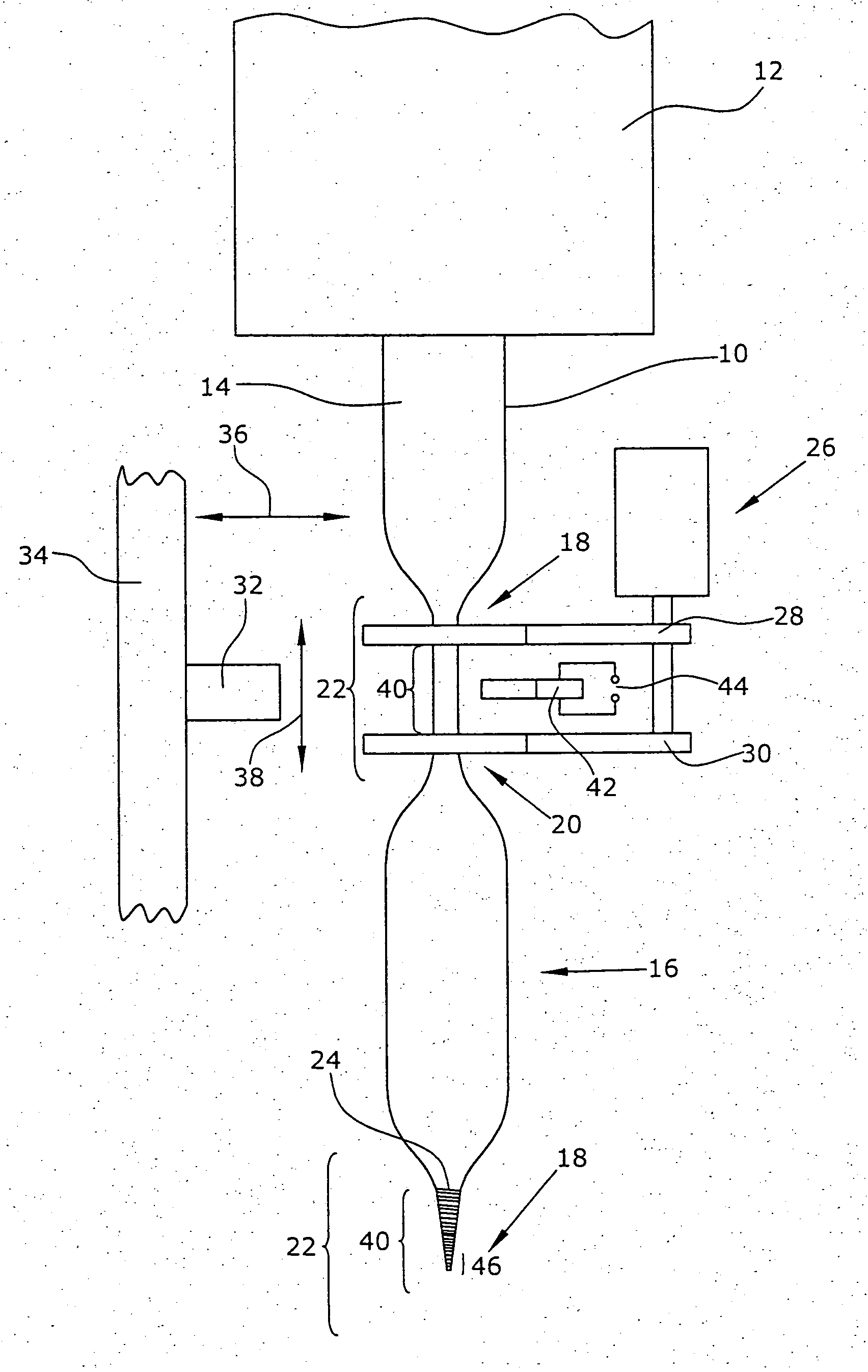
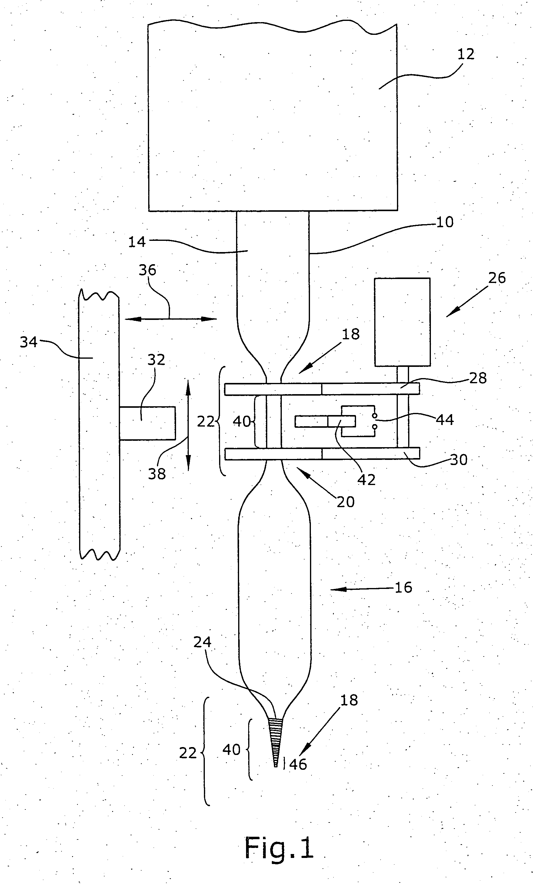
[0032] FIG. 1 shows that a tube 10 is filled with a material, particularly a food, within a filling means 12. By the dead weight of a filled tube 14, it is transported downward without requiring a transport device of its own. The filled tube 14 is separated into individual tubular packs 16 comprising a first end 18 and a second end 20 by which the tubular pack 16 is limited.

[0033] The tube 14 filled with the material comprises a displacement area 22 that is to be wound with an embracing means 24. To this end, the filled tubular pack 14, in the illustrated embodiment, is first gripped, in the displacement area 22 by means of a displacing means 26 comprising two grippers 28,30 formed as two clamps. Subsequently, the grippers 28,30 are moved away from each other so that a large part of the material is displaced out of the displacement area 22.

[0034] Subsequently, a winding means 32 mounted at a carrier 34 is conducted in the direction of the arrow 36 into the displacement area 22 locat...


PUM

PropertyMeasurementUnit
embracing angleaaaaaaaaaa
winding angleaaaaaaaaaa
displacementaaaaaaaaaa

Abstract

For manufacturing tubular packs (16) filled with a material, a tube (14) filled with a material is first wound with an embracing means (24) in at least two displacement areas (22). The winding of the filled tube (14) with the embracing means (24) is effected over at least an entire circumference so that an embracing angle of more than 360° is formed, precisely one winding area (40) being produced in the respective displacement area (22). Since the holding force of the embracing means (24) clearly increases with the embracing angle, the strength of the winding in the displacement area (22) of the tube (14) can be increased by selecting a correspondingly large embracing angle whereby the tightness is improved. Further, the embracing means (24) is fixed in the displacement area (22) so that the embracing means (24) cannot unwind and the tubular pack (16) is tightly sealed. Thus, a particularly tight seal of the tubular pack (16) is produced by winding which also remains tight by fixing.

Description

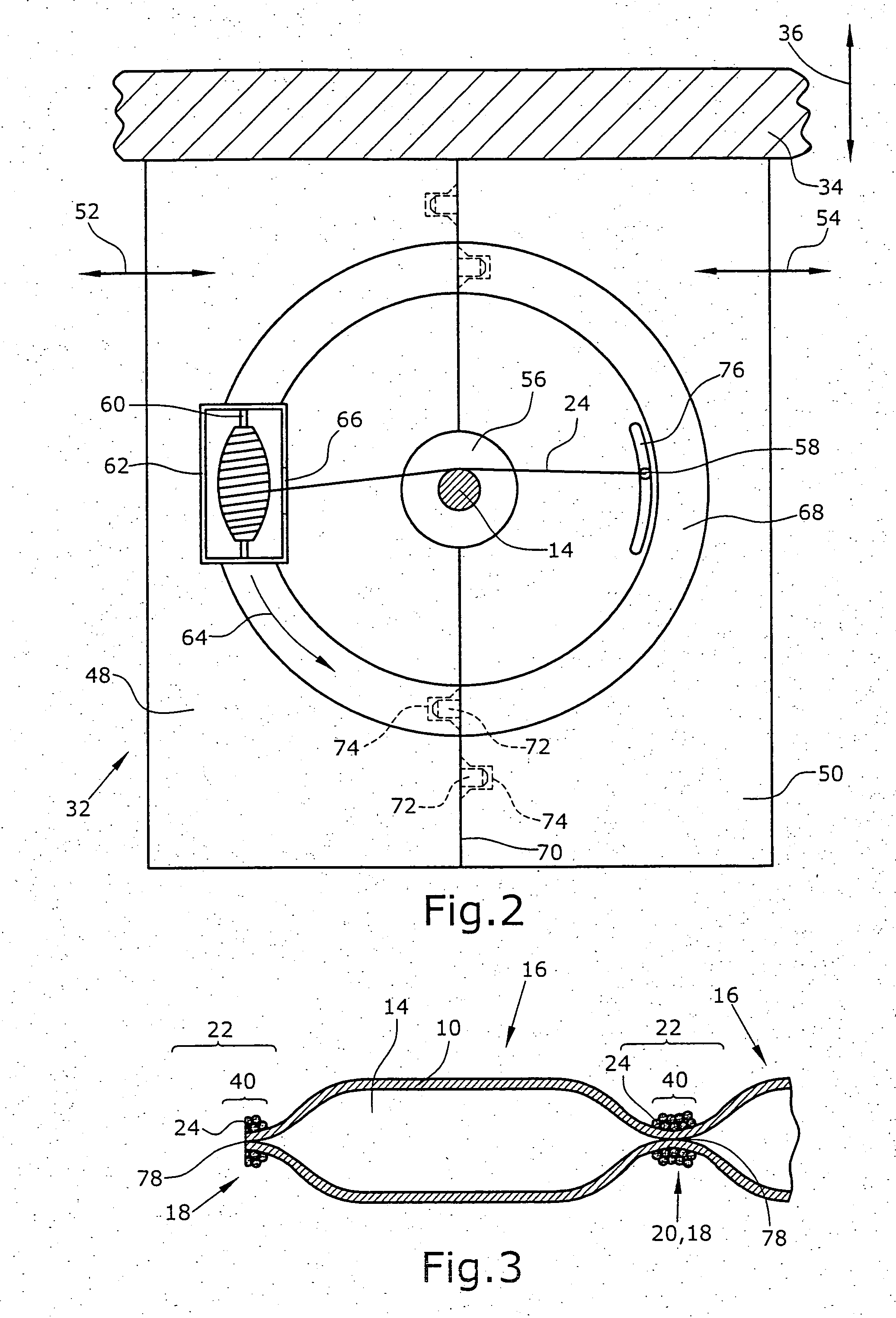
[0001] 1. Field of the Invention[0002] The invention relates to a method and a device for manufacturing tubular packs filled with a material, particularly a food or chemical products (silicones, adhesives, explosives) as well as such a tubular pack. Such tubular packs, for example, are used for packing spreadable sausage and the like. Further; such tubular packs are suitable for packing chemical products, particularly silicones and adhesives as well as for packing explosives.[0003] Usually, tubular packs are filled with the respective material and closed by a metal sealing clamp at regular intervals. The tubular pack is an endless material so that the sealing clamps are arranged such that between two successive sealing clamps, a tubular pack filled with a material and a non-filled tubular section are alternately formed. To manufacture a separate tubular pack filled with a material, the tubular pack is separated by cutting in the non-filled section after it has been sealed by sealing...

Claims


Application Information

Patent Timeline
Patent Type & Authority Applications(United States)
IPC IPC(8): B65B9/12B65B51/08
CPCB65B9/12B65B51/08
Inventor VERMEE, FRANS
Owner FRANS VERMEE
Learn More