Method for manufacturing alkaline battery

Active Publication Date: 2004-11-11
MURATA MFG CO LTD
1 Cites 30 Cited by

AI-Extracted Technical Summary

Problems solved by technology

However, the mask 21 is deformed by heat generated in sputtering or the like to cause position dispersion with respect to the negative electrode cup 4 mounted on the mask 21, so that the stannum coating layer 10 can not be favorably formed on the negative electrode cup 4, which results in inconvenience when mass production of the negative electrode cup 4 is conducted.
Further, such deformation generates gap between the negative electrode cup 4 and the negative electrode cup mounting portion 21C, so that there occurs po...

Benefits of technology

0019] According to the method for manufacturing an alkaline battery of the present invention, there is provided the mask in which, for example, the diameter of the mask opening on the negative electrode cup mounting side A is approximately 5 mm, the depth from the negative electrode mounting surface 11d to the mask opening E is thickened into approximately 5 mm, which is conventionally 0.2 mm, and the tapered angle of the mask opening on the negative electrode cup mounting side is made to be 45.degree.. As described above, since the plate is made thicker and ...

Abstract

In a method in which the inside surface of the negative electrode cup 4 of an alkaline battery having a positive active material of silver oxide or manganese dioxide, a negative active material of zinc or zinc alloy without containing mercury, a separator and a gasket provided between positive electrode mixture and negative electrode mixture, and alkaline electrolyte injected, is coated with metal or metal alloy having a higher hydrogen overpotential than copper, the mask 11 used for coating processing has the shape in which: when d is the diameter of the negative electrode cup, t is the plate thickness of the negative electrode cup, A is the diameter of the mask opening on the negative electrode cup mounting side, B is the diameter of the mask opening on the negative electrode cup supplying side, h is the depth of the negative electrode cup, C is the thickness of mask on negative electrode cup mounting side, and D is a tapered angle of the mask opening on the negative electrode cup, 2(2t+d)-B>A >=0.7d, (A/2)-h>=C>0 mm, and 90°>D>=45°0 are satisfied to coat only the inside surface area except a cuff portion 4a and cuff bottom portion 4b of the negative electrode cup 4.

Application Domain

Silver accumulatorsFinal product manufacture +11

Technology Topic

Silver oxideMetal alloy +5

Image

  • Method for manufacturing alkaline battery
  • Method for manufacturing alkaline battery
  • Method for manufacturing alkaline battery

Examples

  • Experimental program(10)

Example

5.20 80 4.16 5.0 > A .largecircle. X 0 Practice Example 2 5.20 90 4.68 5.0 > A .largecircle. X 0 Comparative Example 1 5.20 70 3.64 5.0 > A .DELTA. X 7 Comparative Example 2 5.20 100 5.20 5.0 < A .largecircle. .DELTA. 35 Comparative Example 3 5.20 -(*2) -(*2) -- .largecircle. .largecircle. 100 (*1) Evaluation of coating state .largecircle.: coated, .DELTA.: coated but base material is seen, X: not coated (*2) In comparative example 2, mask is not used.

Example

[0037] Hereupon, in a practice example 1 of Table 1 the negative electrode cup 4 is formed as follows. First, a three-layer clad member made of nickel 7, stainless 8, and copper 9, having the plate thickness t=0.2 mm is pressed to form, as shown in FIG. 4, a negative electrode cup having the inside diameter d=5.20 mm of an alkaline battery, for example, SR626SW.
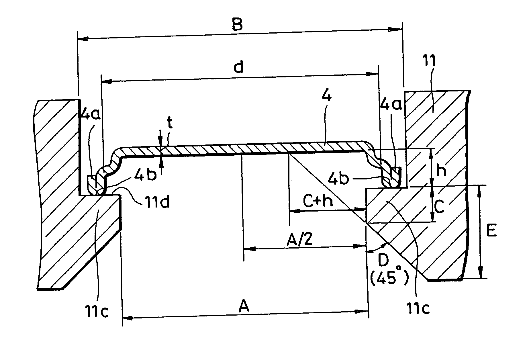
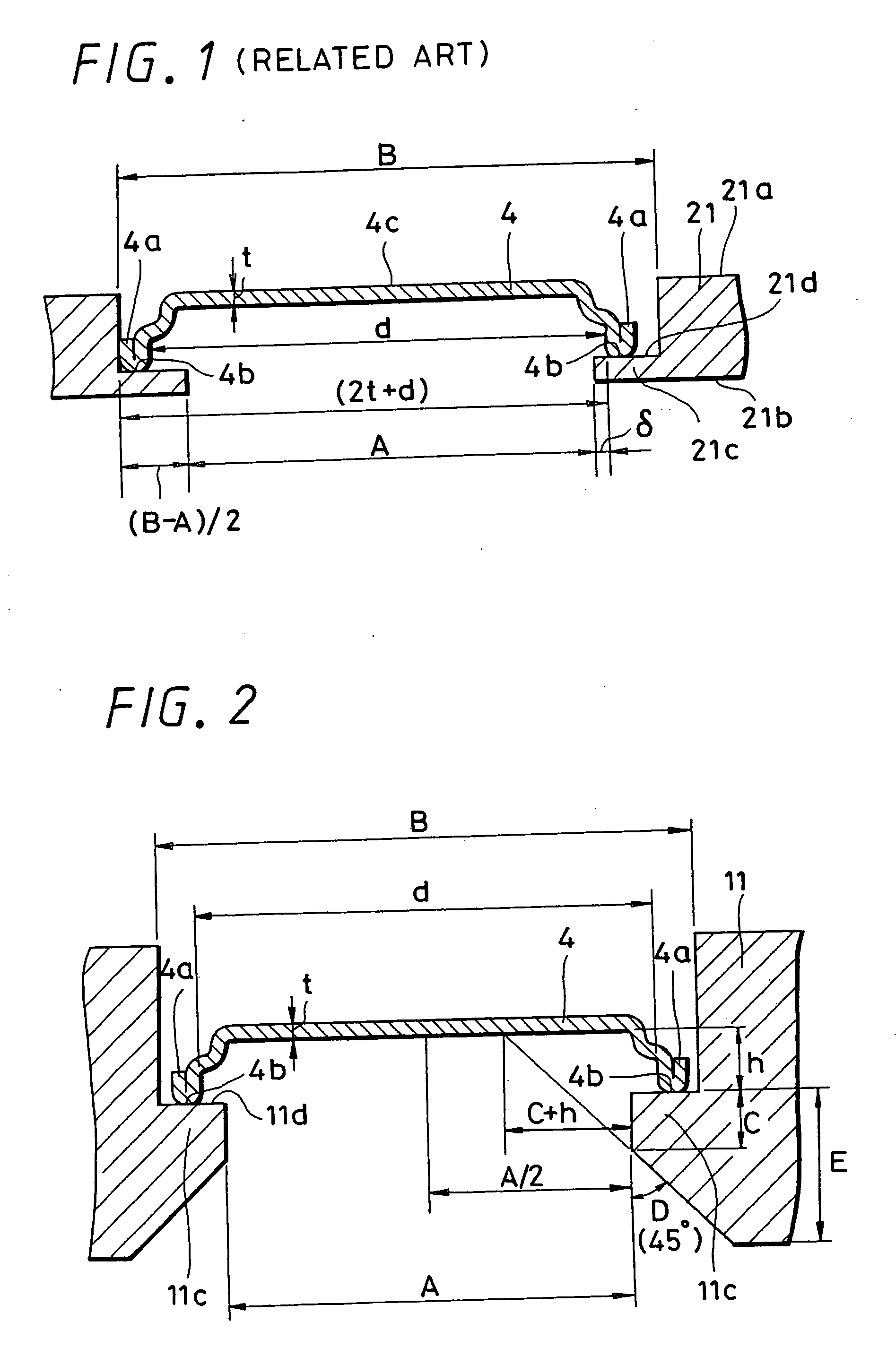
[0038] Next, the mask 11 for partly forming a film is prepared, in which the thickness of the mask on the negative electrode cup mounting side is 0.2 mm in FIG. 2.
[0039] Then, the negative electrode cup 4 is set on the mask 11 that covers the cuff portion 4a and cuff bottom portion 4b of the negative electrode cup 4 and sputtering is performed, so that the negative electrode cup 4 in which the coating layer 10 of approximately 0.01 .mu.m made of stannum that is an example of metal having high hydrogen overpotential is provided on the inside surface area thereof.
[0040] Hereupon, when A is the diameter of opening of the mask 11 and d is the inside diameter of the negative electrode cup 4, A/d is defined as a mask opening ratio, and in the practice example 1, sputtering is performed with the opening ratio of mask 11 on the negative electrode cup mounting side being 80% (opening diameter A=4.16 mm) and opening diameter of mask 11 on the cup supplying side B being 6.20 mm, that is, 2(2t+d)-B=5.0 mm>A(=4.16 mm). In the practice example 1, an alkaline battery in button shape shown in FIG. 3 is manufactured using the above described negative electrode cup 4.
[0041] Specifically, as shown in FIG. 3, alkaline electrolyte consisting of sodium hydroxide aqueous solution of 28% by weight is injected into the positive electrode can 2; then a pellet of coin shape formed of positive electrode mixture 1 containing silver oxide, manganese dioxide, and polyethylene tetrafluoride is inserted; and the alkaline electrolyte is impregnated into the positive electrode mixture.
[0042] Then, a separator 5 of a punched out circular shape having a three-layer structure made of graft-polymerized film formed of polyethylene and cellophane laminated and non woven fabric is set on the pellet of the positive electrode mixture 1; and the gasket 6 of nylon 66 coated with nylon 610 is set.
[0043] Next, alkaline electrolyte of sodium hydroxide aqueous solution of 28% by weight is dropped onto the non woven fabric of the separator 5 to be impregnated. Further, the gel-state negative electrode mixture 3 composed of zinc alloy powder without mercury, containing aluminum (Al), indium (In), and bismuth (Bi); thickener; and sodium hydroxide aqueous solution is loaded; and then the negative electrode cup 4 is mounted on the negative electrode mixture 3.
[0044] Then, the positive electrode can 2 is swaged and caulked to manufacture an alkaline battery, for example, SR626SW in button shape and the alkaline battery of the practice example 1 is thus obtained.

Example

[0045] Further, the negative electrode cup 4 of a practice example 2 in Table 1 is subjected to sputtering similar to the practice example 1 except that the opening ratio of the mask 11 on the negative electrode cup mounting side A/d is 90% (opening diameter A=4.68 mm). In this case, 2(2t+d)-B=5.0 mm>A(=4.68 mm) is obtained. The above negative electrode cup 4 is used in an alkaline battery of the practice example 2, the other structure of which is similar to the practice example 1, to manufacture the alkaline battery of button shape, such as SR626SW.

PUM

PropertyMeasurementUnit
Angle90.0°
Thickness
Diameter

Description & Claims & Application Information

We can also present the details of the Description, Claims and Application information to help users get a comprehensive understanding of the technical details of the patent, such as background art, summary of invention, brief description of drawings, description of embodiments, and other original content. On the other hand, users can also determine the specific scope of protection of the technology through the list of claims; as well as understand the changes in the life cycle of the technology with the presentation of the patent timeline. Login to view more.

Similar technology patents

Energy saver cycle

InactiveUS20160208428A1energy savelong operation
Owner:MABE SA DE CV

Polishing composition and method for polishing synthetic resin

PendingUS20220025212A1suitable for use
Owner:FUJIMI INCORPORATED

Medical device for treating cardiac arrhythmia

ActiveUS20180036541A1suitable for use
Owner:MICROPORT SORIN CRMSHANGHAICO LTD

Endothelin receptor type a activity regulating antibody

PendingUS20220153831A1prevent hypertensionsuitable for use
Owner:HEDGEHOG INC

Solid oxide proton conductor system and method of operating same for enhanced proton transport

ActiveUS8148031B2increase proton transfer ratesuitable for use
Owner:COLLEGE OF WILLIAM & MARY

Filter module and system having spirally wound membrane filters, and method for the production thereof

InactiveUS9050564B2high pressure resistancesuitable for use
Owner:MN BET

Burnpot for solid particulate stove

InactiveUS20080110448A1reduce carbon buildupreduce cleaning
Owner:HNI TECH INC

Classification and recommendation of technical efficacy words

  • reduce cleaning
  • long operation

Burnpot for solid particulate stove

InactiveUS20080110448A1reduce carbon buildupreduce cleaning
Owner:HNI TECH INC

Energy saver cycle

InactiveUS20160208428A1energy savelong operation
Owner:MABE SA DE CV
Why Eureka
Try Eureka