
Chlorine dioxide from a methanol-based generating system as a chemical feed in alkali metal chlorite manufacture

Inactive Publication Date: 2004-11-18
SUPERIOR PLUS INC
View PDF11 Cites 10 Cited by
  • Summary
  • Abstract
  • Description
  • Claims
  • Application Information

AI Technical Summary

Benefits of technology

[0028] However, it has now been surprisingly found that, by carrying out the chlorite manufacture according to the process of the present invention and described in detail below, the resulting product is significantly purer than originally anticipated. The process of the present invention permits the more economical methanol to be used as the reducing agent in the generator of the chlorine dioxide and in alkali metal chlorite manufacture.
[0045] Incorporation of the process equipment of this invention (gas conditioning, chlorite reactor, etc) with an existing chlorine dioxide generator also makes it possible to optimize ClO.sub.2 plant operation by minimizing the need for:

Problems solved by technology

A major drawback of all of the above described processes is that the final product has a high content of certain impurities, particularly carbonates and bicarbonates.
Such a high level of carbonates is detrimental at the point of use of the alkali metal chlorite, in particular when chlorite is converted to chlorine dioxide to be used for water disinfection or pulp bleaching.
The presence of carbonates causes the formation of scale in the equipment employed for chlorine dioxide generation, resulting in higher operating costs and troublesome maintenance.
While there are known methods for the purification of sodium chlorite from the carbonate impurity, they are very costly and often they create more problems than they solve.
138) may result in the contamination of chlorite with highly poisonous lead compounds, rendering the product unsuitable for water treatment applications.
Unfortunately, hydrogen peroxide is a rather expensive reducing agent and therefore its use is not always economically viable.
Unfortunately, the use of the latter reducing agent has a major drawback, namely the co-production of a highly undesired chlorine by-product, which has to be separated from chlorine dioxide and separately utilized or otherwise disposed of.

Method used


Image

  • Chlorine dioxide from a methanol-based generating system as a chemical feed in alkali metal chlorite manufacture
  • Chlorine dioxide from a methanol-based generating system as a chemical feed in alkali metal chlorite manufacture
  • Chlorine dioxide from a methanol-based generating system as a chemical feed in alkali metal chlorite manufacture

Examples


example

[0059] This Example illustrates the preparation of sodium chlorite with low carbonate and organic content according to the process of the invention.

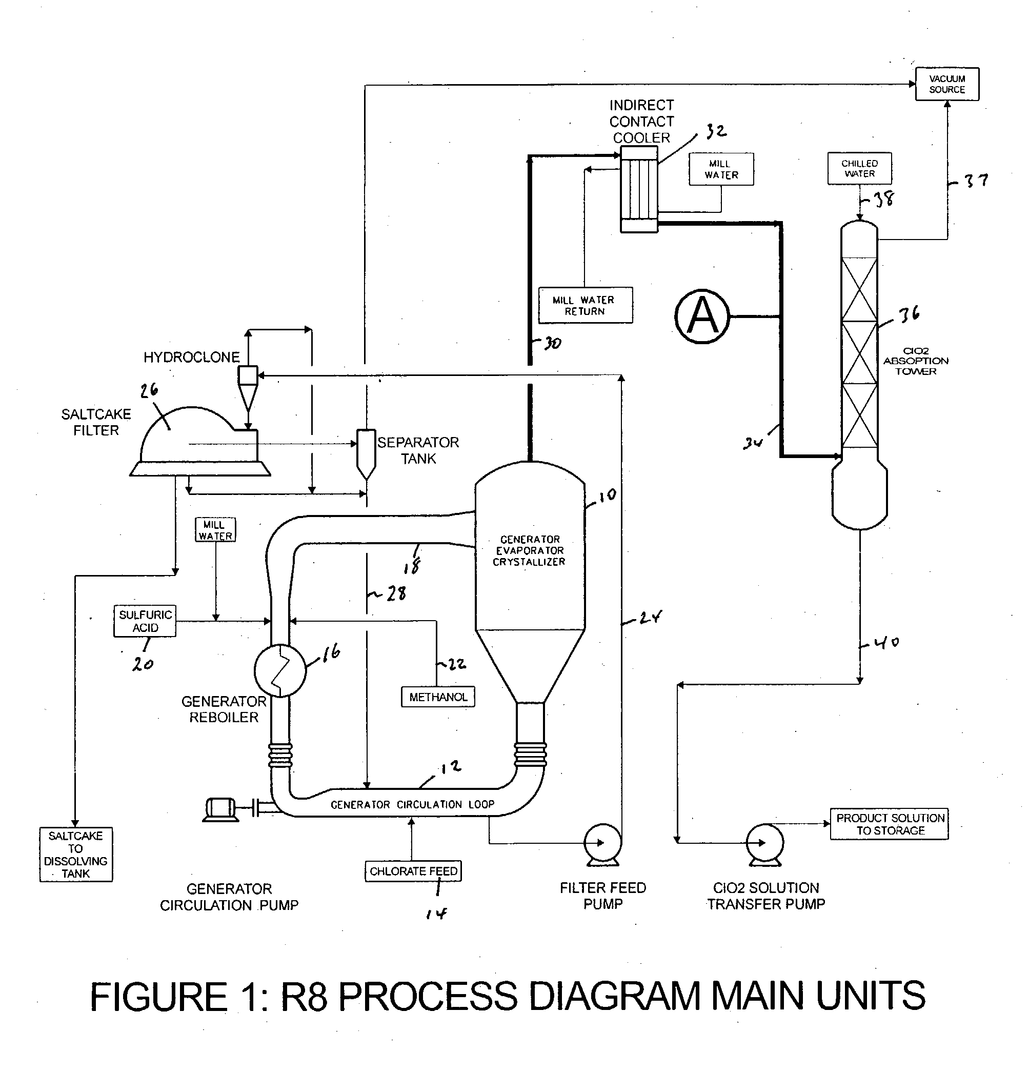
[0060] A commercial, subatmospheric, methanol-based ClO.sub.2 generator (R8) as shown in FIG. 1 was run in the vicinity of its nominal capacity (20 MTPD) and within its typical liquor composition and pressure / temperature operating ranges: 7.5 to 8.5 N acidity, 1.8 to 2.2 M sodium chlorate concentration, 119 to 121 mmHg absolute pressure and 69 to 71.degree. C.

[0061] Methanol consumption was 0.174 g / g ClO.sub.2, ICC exit temperature was 10.degree. C. and ClO.sub.2 product solution strength was 12.5 g / L.

[0062] Following several hours of steady operation, an off-gas sample started to be continuously withdrawn from a port at the top of the ICC exit line (See point A in FIG. 1). The gases were directed into a 150 mL gas washing bottle (pretreatment stage) followed by a chlorite reaction bottle filled with 100 mL water+37 mL 50% NaOH+17 mL 50%...


PUM


Abstract

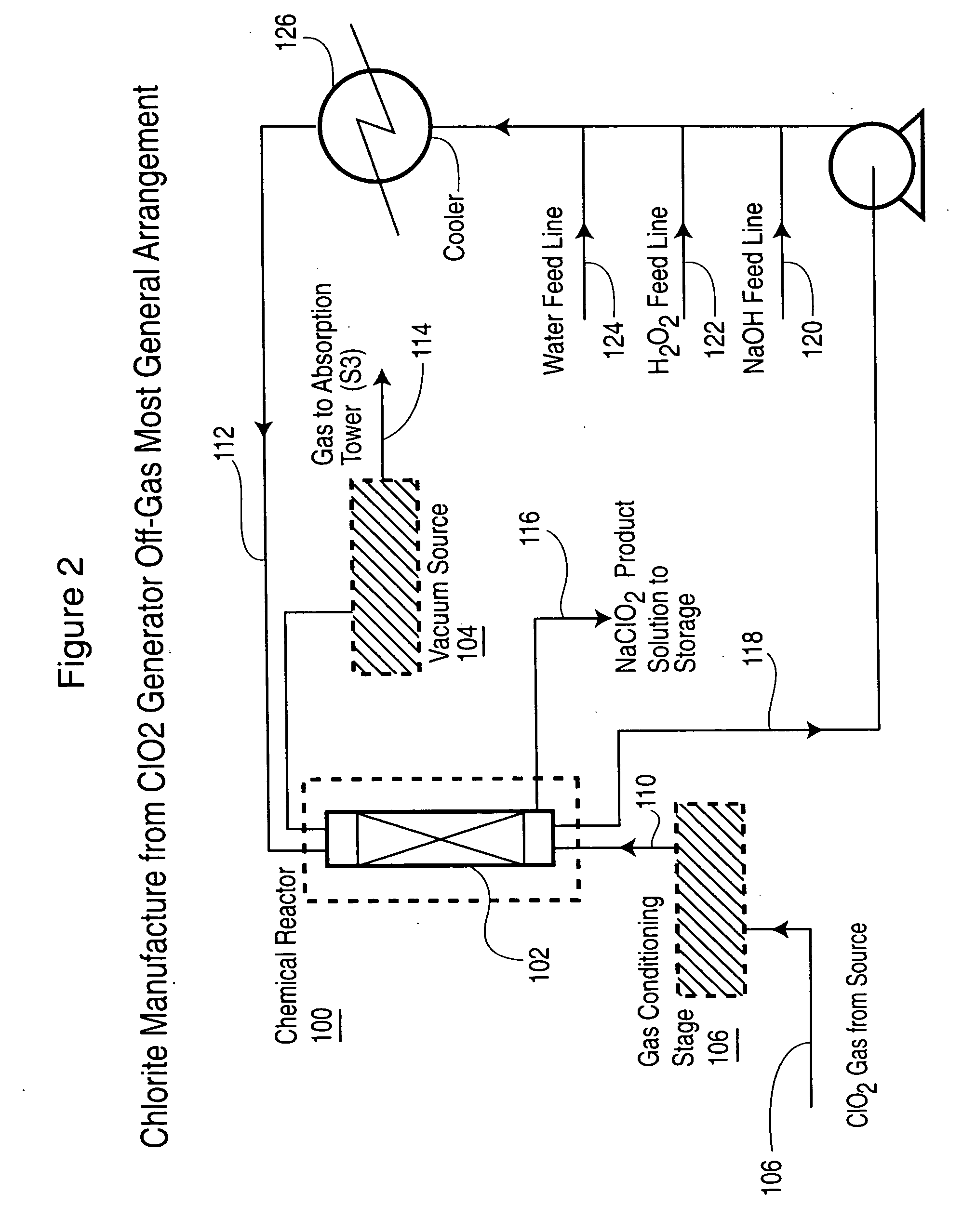
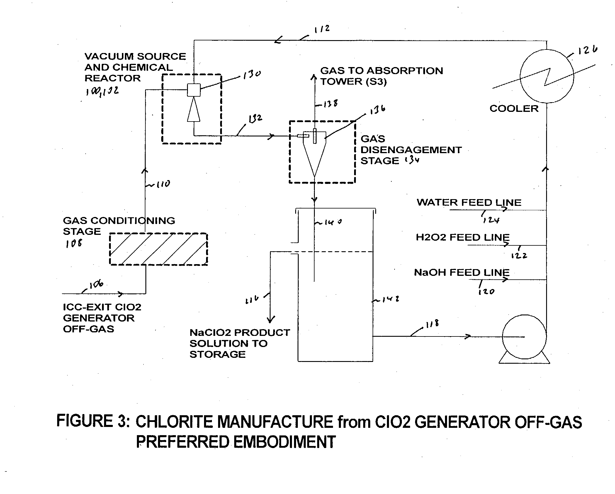
Alkali metal chlorite, particularly sodium chlorite, is produced with a level of purity superior to that expected based on the composition of the chlorine dioxide generator off-gas that is used as a raw chemical feed for chlorite manufacture. The off-gas is preferably drawn before it enters the chlorine dioxide absorption tower and is passed through a conditioning stage to then react in a liquid medium to produce an alkali metal chlorite solution from which the unreacted and produced gases are immediately separated.

Description

[0001] This invention relates to a process for the manufacture of alkali metal chlorite solutions with very low level of impurities by reduction of chlorine dioxide originating from a subatmospheric, methanol-based chlorine dioxide generation process.BACKGROUND TO THE INVENTION[0002] Alkali metal chlorites are well known precursors of chlorine dioxide with a wide range of applications, mainly in water treatment, pulp bleaching and textile bleaching. Chlorites are prepared typically by the reaction of chlorine dioxide, a reducing agent and an alkali. An exhaustive discussion of various preparative methods for chlorite synthesis can be found in the basic textbook entitled: "Chlorine Dioxide. Chemistry and Environmental Impact of Oxychlorine Compounds" by W. J. Masschelein, 1979, pp. 130 to 145, the disclosure of which is incorporated herein by reference.[0003] Various improvements to the basic concept of reacting chlorine dioxide with the reducing agent and alkali to form chlorite are...

Claims


Application Information

Patent Timeline
IPC IPC(8): C01B11/02C01B11/10
CPCC01B11/023C01B11/10
Inventor COSTA, MARIO LUISCOWLEY, GERALDPU, CHUNMIN
Owner SUPERIOR PLUS INC
Learn More