Spin valve magnetoresistive device with enhanced performance

a technology of magnetoresistive devices and spin valves, which is applied in the field of spin valve magnetoresistive devices, can solve the problems of high resistance of tunnel junction devices, large amount of shot noise, and device sensitivity not very satisfactory,

Inactive Publication Date: 2004-12-09
COMMISSARIAT A LENERGIE ATOMIQUE ET AUX ENERGIES ALTERNATIVES
View PDF3 Cites 40 Cited by
  • Summary
  • Abstract
  • Description
  • Claims
  • Application Information

AI Technical Summary

Problems solved by technology

But these devices are not very satisfactory in terms of sensitivity.
The resistance of tunnel junction devices is too high, which introduces a large amount of shot noise.
Therefore this is not desirable.
These values are too small compared with the contact resistances with current input electrodes, and the resistances of the electrodes themselves.
In random access memories, the high resistance of the tunnel junction has the disadvantage that it leads to a high memory time constant which limits its operating frequency.

Method used


Image

  • Spin valve magnetoresistive device with enhanced performance
  • Spin valve magnetoresistive device with enhanced performance
  • Spin valve magnetoresistive device with enhanced performance

Examples


Embodiment Construction

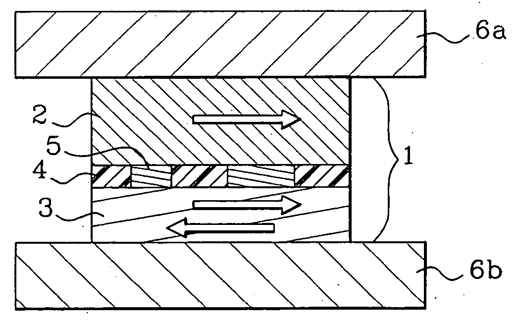
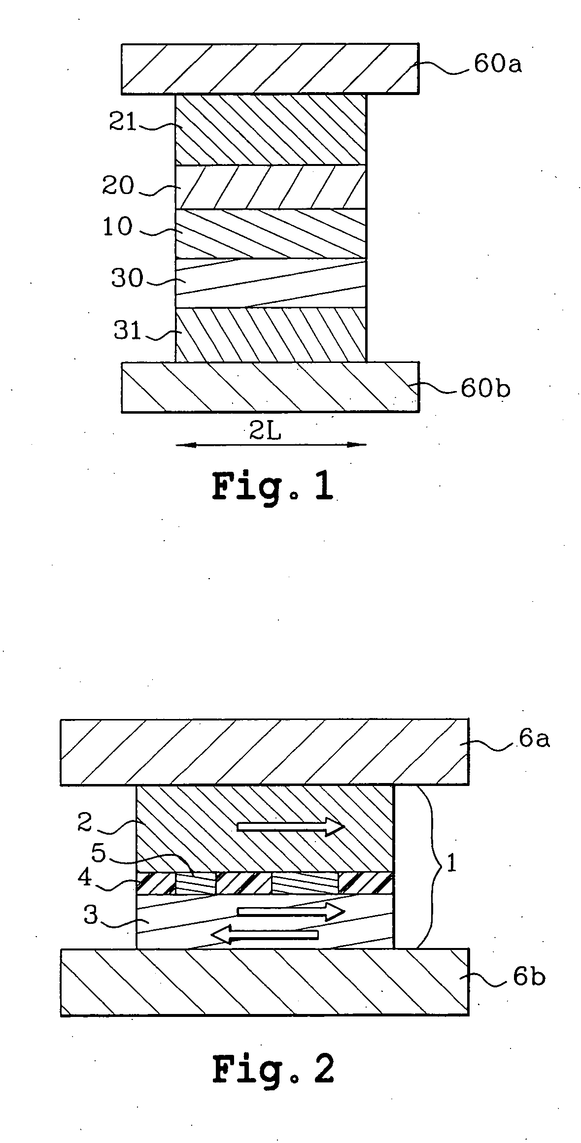
[0053] FIG. 2 shows an example of a basic configuration of a magnetoresistive spin valve device according to the invention. As we have already seen, a spin valve with a perpendicular current comprises at least two magnetic layers for which the relative orientation of their magnetisation directions can vary under the effect of a magnetic field. At least one of the magnetic layers has a free magnetisation direction. To simplify the diagrams and descriptions, the examples shown in the following part of this description apply to a structure for which one of the magnetic layers has a free magnetisation direction and the other has a fixed magnetisation direction. The directions of magnetisation could have been free for the two magnetic layers, and it would be easy to adapt one of the structures to the other.

[0054] The device in FIG. 2 comprises a spin valve 1 that is a stack of layers with magnetic layers 2, 3, at least one of which is a so-called trapped magnetic layer 2 and at least one...


PUM

PropertyMeasurementUnit
thicknessaaaaaaaaaa
thicknessaaaaaaaaaa
RAaaaaaaaaaa

Abstract

The invention relates to a magnetoresistive device with a spin valve (1) formed from a stack of layers including at least two magnetic layers (2, 3) for which the relative orientation of their magnetisation directions can vary under the influence of a magnetic field, and comprising means (6a, 6b) of circulating a current in the spin valve transverse to the plane of the layers. The spin valve (1) comprises at least one discontinuous dielectric or semiconducting layer (4) in the stack, with electrically conducting bridges (5) passing through the thickness of the dielectric or semiconducting layer, these bridges (5) being designed to locally concentrate the current that passes transversely through the stack. Application particularly suitable for magnetic read heads, and random access memories.

Description

TECHNICAL DOMAIN[0001] This invention relates to a magnetoresistive device with a spin valve. This device is used in applications for ultra-high density magnetic recording, as a sensitive element in magnetoresistive read heads for magnetic tapes and for computer hard disks. Another application of this device is for making memory dots and MRAM (Magnetic Random Access Memory) type memories.STATE OF THE PRIOR ART[0002] In the field of magnetic read heads and magnetic random access memories, magnetoresistive spin valve devices which have a spin valve formed by a stack of layers with a separating layer sandwiched between two magnetic layers were not used until recently. The relative orientation of the magnetisation directions of these layers may vary under the influence of a magnetic field. In some devices, the two magnetic layers have a free magnetisation direction. In this case, the two extreme positions in which the two magnetisation directions are parallel or anti-parallel are used, ...

Claims


Application Information

Patent Timeline
Patent Type & Authority Applications(United States)
IPC IPC(8): G11B5/39G11C11/16H01F10/16H01F10/30H01F10/32H01F41/30H01L21/8246H01L27/105H01L43/08H01L43/10
CPCB82Y10/00B82Y25/00B82Y40/00G11B5/3903Y10T29/49044H01F10/3254H01F41/307H01L43/08G11C11/16G11C11/161H10N50/10
Inventor DIENY, BERNARDRODMACQ, BERNARDERNULT, FRANCK
Owner COMMISSARIAT A LENERGIE ATOMIQUE ET AUX ENERGIES ALTERNATIVES
Why Eureka
Try Eureka