Vibro-acoustic engine diagnostic system

a technology of vibration and engine, applied in the direction of instruments, analogue processes for specific applications, electric/magnetic computing, etc., can solve the problems of production bottleneck, lack of consistency and focus, and lack of human experts

Inactive Publication Date: 2004-12-23
INTELLIGENT MECHANTRONIC SYST INC
View PDF14 Cites 28 Cited by
  • Summary
  • Abstract
  • Description
  • Claims
  • Application Information

AI Technical Summary

Problems solved by technology

This creates a production bottleneck if an inadequate number of expert technicians is available.
Moreover, with the large number of produced engines, human experts, who are subjective in nature, would lack consistency and focus.
Examples of these faults are misfiring, knocking, valve leakage (intake and exhaust), fuel leakage or shorting, cylinder ring gumming, cylinder ringing, bearing wear, gear damage, worn timing belt, etc.
As such, faults are expected to manifest themselves in the engine vibration and sound signatures.
However, detecting small faults is limited by the signal to noise ratio, signal path attenuation factor, and the discrimination ability of the selected diagnostic technique.
However, these techniques are not suitable for engine diagnostics, as engine vibration signature is non-stationary in nature.
However, most of these techniques are used in engine noise analysis or for a specific combustion related faults such as over-fueling or piston slapping.
However, hot testing is performed only on completely assembled engines.

Method used


Image

  • Vibro-acoustic engine diagnostic system
  • Vibro-acoustic engine diagnostic system
  • Vibro-acoustic engine diagnostic system

Examples


Embodiment Construction

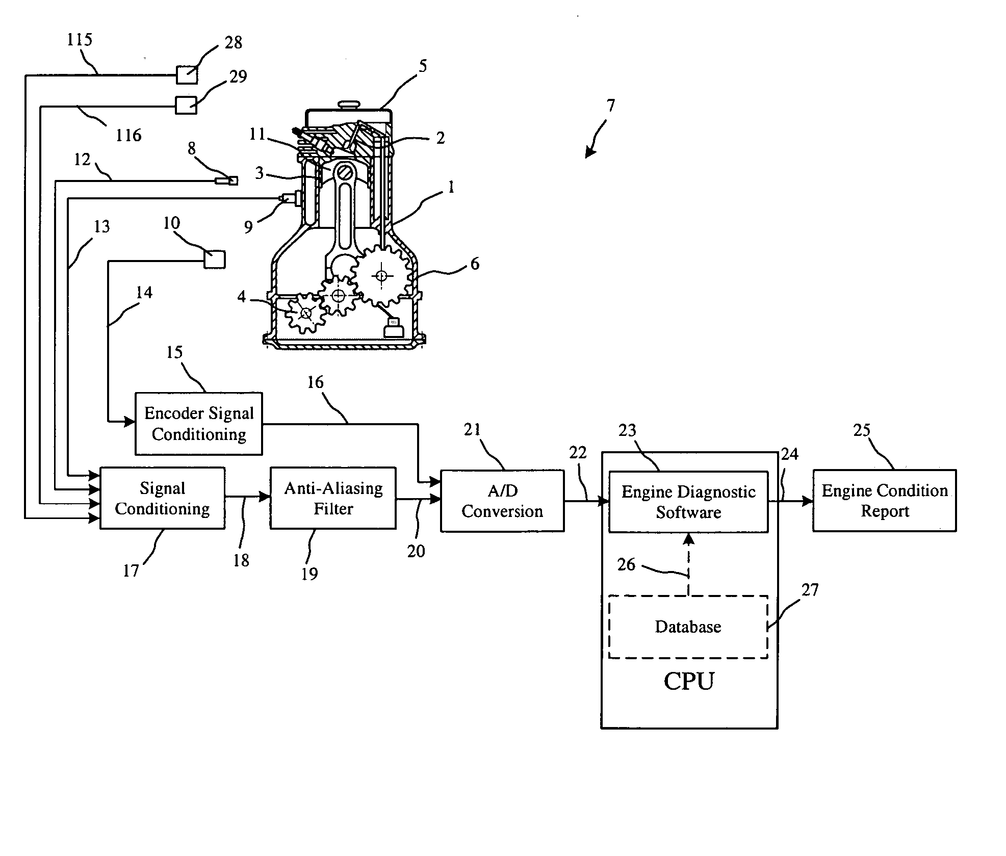
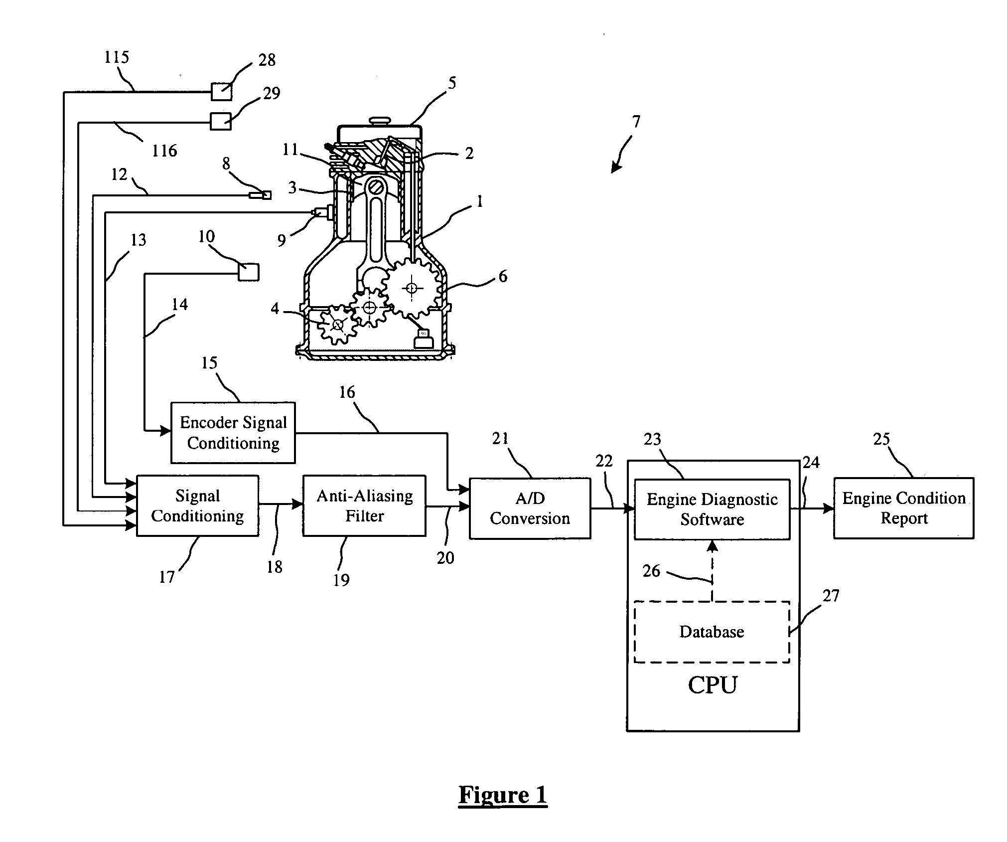
[0030] FIG. 1 illustrates an engine diagnostic system 7 for detecting faulty mechanical parts in an internal combustion engine 1. Briefly, the system includes at least one vibration sensor (accelerometer) 9, at least one sound sensor (microphone) 8, encoder 10, at least two vacuum sensors 28, 29 (for cold testing), signal conditioning and filtering circuits 15, 17, 19, A / D signal converter 21, and engine diagnostic software 23. Although three internal components of an internal combustion engine; namely, valves 2, gears 4, and oil rings 3, are illustrated as examples, it should also be understood that more engine components can be added once their distinguishing feature frequencies are detected by sensors 8 and 9.

[0031] At the quality assurance cell, the subject engine is first placed at a designated place and the encoder 10 and the vibration sensor 9 are clamped to the engine. In the cold test case, the encoder 10 is preferably attached permanently to the electric motor (not shown)....


PUM


Abstract

A diagnostic system is used for detecting the health condition of moving internal mechanical components in internal combustion engines. The system uses measurements of engine vibration and acoustic signals during cold or hot engine test. The system includes engine vibration and acoustic sensing, engine vacuum sensing, signal conditioning and pre-filtering, analog to digital conversion, advanced digital signal processing, and decision making. Engine vibration and acoustic signals are first amplified and then passed through a low-pass filter. The signals are then digitized and sent to a computer. An engine diagnostic software receives the digitized data and performs digital filtering to isolate signal parts that most influenced by each engine moving mechanical component of interest. Features are then extracted using statistical analysis and passed to a decision making inferences. The decision making inferences utilize fuzzy logic engines to fuse feature values and reach a conclusive decision about each component condition. The system is then summarizes all results and presents them to the operator.

Description

[0001] This application claims priority to U.S. Ser. No. 60 / 477,670 filed Jun. 11, 2003.[0002] 1. Field of the Invention[0003] The present invention is related, in general, to a method for detecting faults in internal combustion engines based on time-frequency analysis of the engine vibration and acoustic measurements.[0004] 2. Background Art[0005] Manufacturing of reliable engines requires thorough testing of each produced engine. The testing process should be performed quickly and accurately. Currently, engine manufacturers rely on expert technicians to evaluate engine health condition. These technicians use their hearing sense and knowledge of engine fault noise characteristics to screen out any faulty engine. Such knowledge is gained by practice and experience, thus, makes the inspection process efficiency depends on the technicians' experience level. This creates a production bottleneck if an inadequate number of expert technicians is available. Moreover, with the large number ...

Claims


Application Information

Patent Timeline
Patent Type & Authority Applications(United States)
IPC IPC(8): G01M15/05G01M15/12G06F19/00G06G7/70
CPCG01M15/05G01M15/12
Inventor BASIR, OTMAN A.
Owner INTELLIGENT MECHANTRONIC SYST INC
Why Eureka
Try Eureka