

Amorphous and nanocrystalline glass-coated articles
a glass coating and nano-crystalline technology, applied in the direction of magnetic bodies, manufacturing tools, transportation and packaging, etc., can solve the problem of difficult wound components to be produced efficiently
- Summary
- Abstract
- Description
- Claims
- Application Information
AI Technical Summary
Benefits of technology
Problems solved by technology
Method used
Image

Examples
example 1
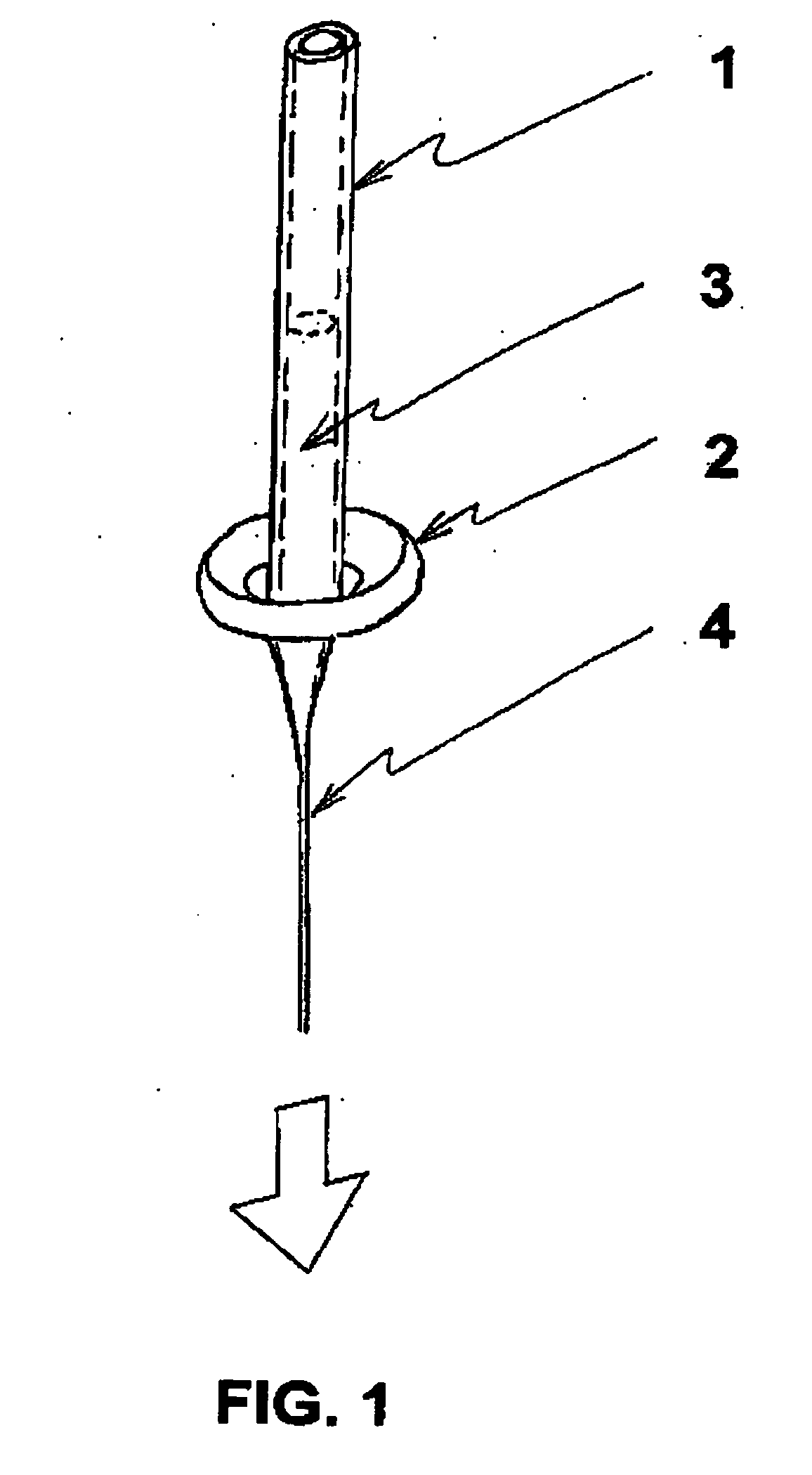
An ingot composed of an amorphous-forming metallic alloy is prepared by loading the appropriate weights of constituent elements into a quartz tube that is sealed at one end. The other end of this quartz tube is connected to a pressure-vacuum system to allow evacuation and back-filling with Ar gas several times to ensure a low oxygen Ar atmosphere within the quartz tube. Next, the closed end of the quartz tube in which the elements reside is introduced into a high frequency induction-heating coil. With the application of radio frequency (“r.f.”) power, the elements inside the tube are caused to heat and melt into a stirred, homogeneous metallic alloy body. When the r.f. power is shut off, the alloy body is allowed to cool to room temperature in the Ar atmosphere. Once cooled, the same metallic alloy body is inserted into the bottom of a vertically disposed glass tube 1 (preform), having 6-mm diameter that is sealed at the lower end, as depicted in FIG. 1. The upper end of this prefo...
example 2
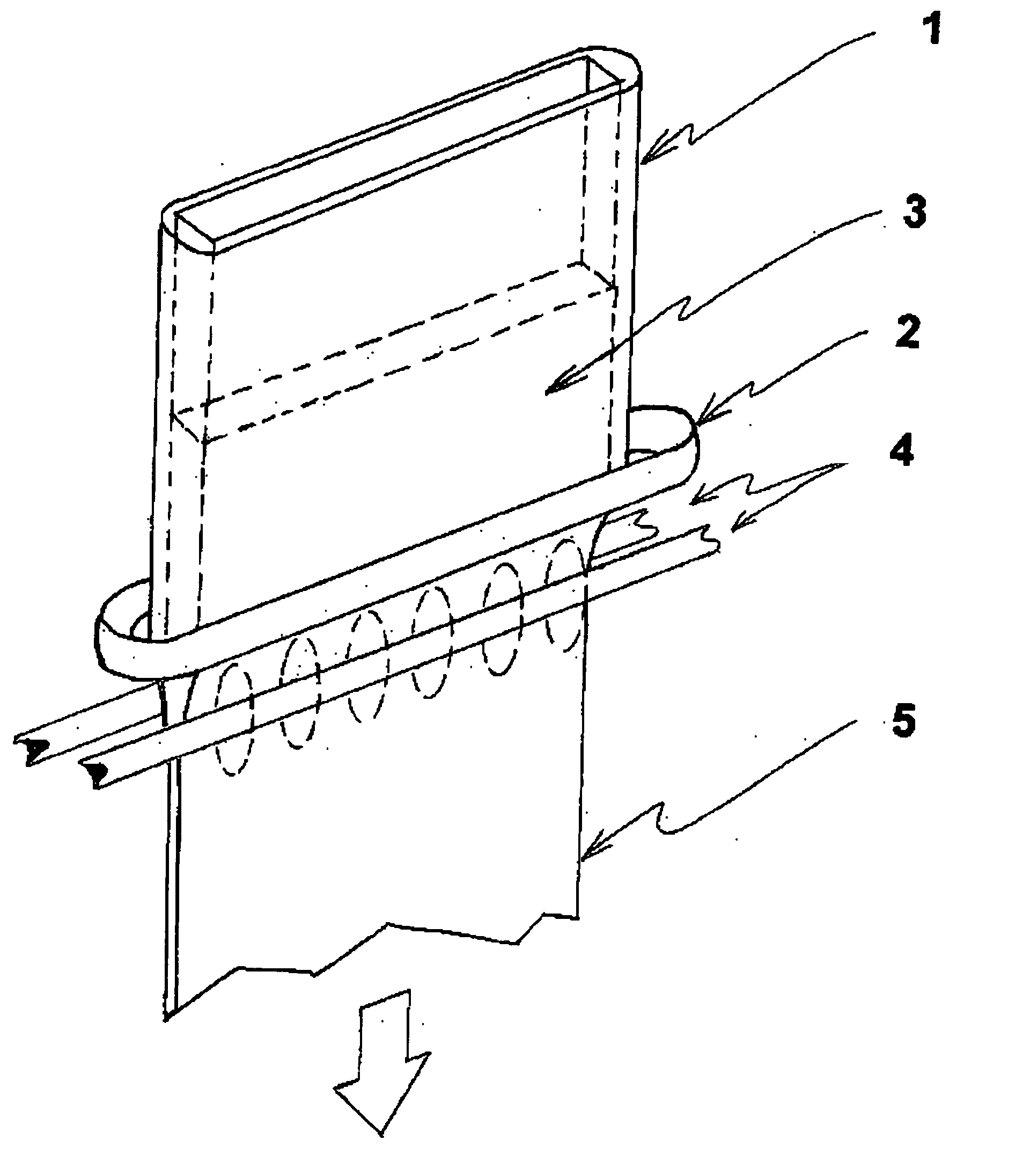
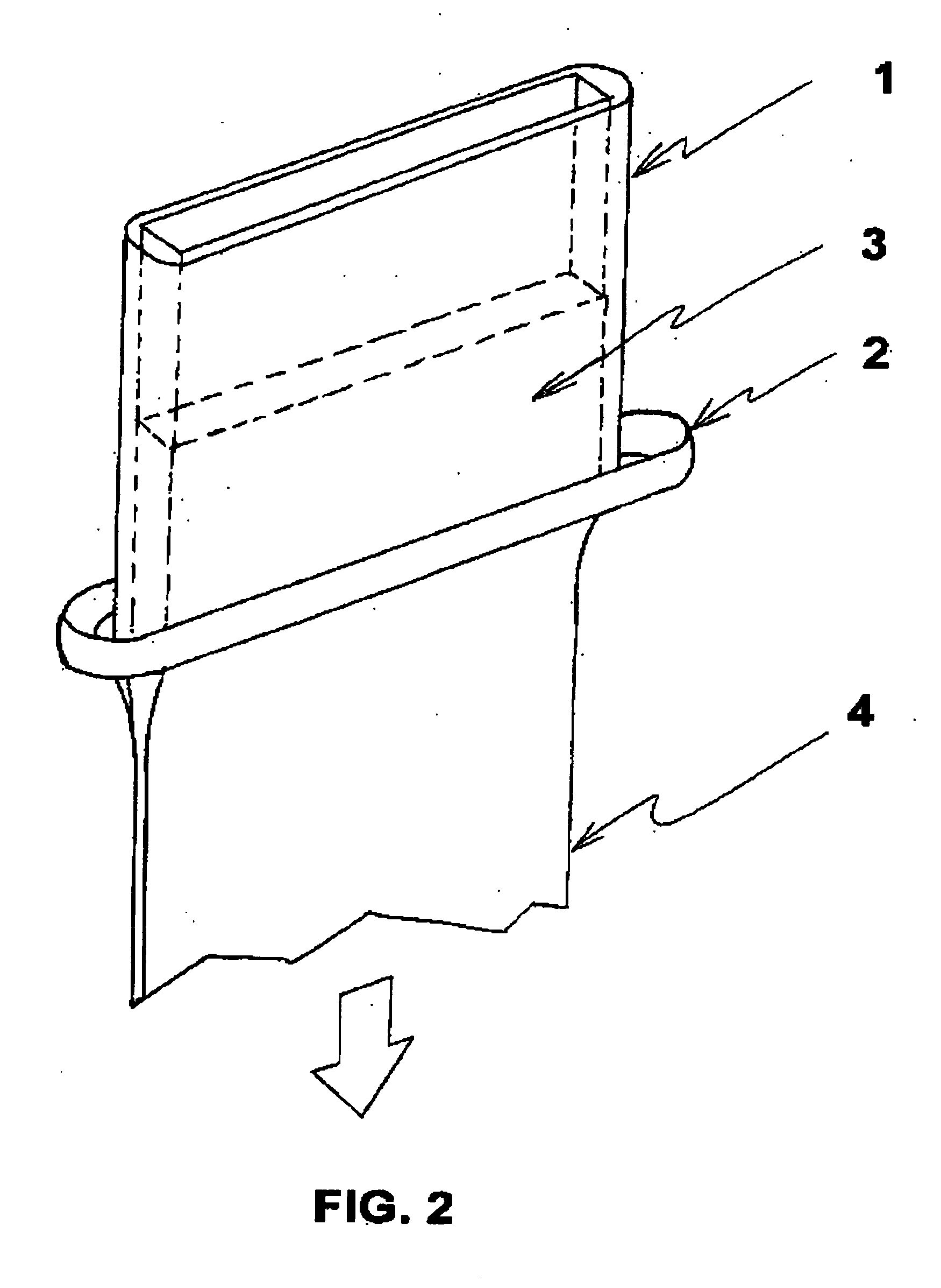
An amorphous glass-coated article having a substantially rectangular rather than a circular cross-section is prepared by the procedure described in Example 1, except that a hollow substantially rectangular rather than a hollow round glass preform is now used.
A pre-melted metallic alloy body is inserted into the bottom of a vertically disposed hollow substantially rectangular glass preform 1, having 6-mm×50-mm internal cavity that is sealed at the lower end, as depicted in FIG. 2. The upper end of this preform is connected to a pressure-vacuum system to allow evacuation and back-filling with Ar gas several times to ensure a low oxygen Ar atmosphere within the quartz tube. A specially built inductor 2 at the bottom of the preform is energized with r.f. power in order to heat and then melt the metallic alloy body 3 within the preform. Once the metallic alloy body is molten and heated above its liquidus temperature by some 20 to 50° C., a solid glass plate is used to touch and bond t...
example 3
An amorphous glass-coated article having a substantially rectangular rather than a circular cross-section is prepared by the procedure described in Example 1, except that a hollow substantially rectangular rather than a hollow round glass preform is now used.
A pre-melted metallic alloy body is inserted into the bottom of a vertically disposed hollow substantially rectangular glass preform 1, having 6-mm×50-mm internal cavity that is sealed at the lower end, as depicted in FIG. 2. The upper end of this preform is connected to a pressure-vacuum system to allow evacuation and back-filling with Ar gas several times to ensure a low oxygen Ar atmosphere within the quartz tube. A specially built inductor 2 at the bottom of the preform is energized with r.f. power in order to heat and then melt the metallic alloy body 3 within the preform. Once the metallic alloy body is molten and heated above its liquidus temperature by some 20 to 50° C., a solid glass plate is used to touch and bond t...
PUM
| Property | Measurement | Unit |
|---|---|---|
| Fraction | aaaaa | aaaaa |
| Fraction | aaaaa | aaaaa |
| Fraction | aaaaa | aaaaa |
Abstract
Description
Claims
Application Information