
Heat dissipating fins of heat sink and manufacturing method thereof

a technology of heat sink and heat dissipation fin, which is applied in the direction of cooling/ventilation/heating modification, semiconductor device details, semiconductor/solid-state device details, etc., can solve the problems of heat dissipation fin thickness proportionality, electronic device performance degradation, etc., to enhance the performance of the heat sink, reduce the conductive thermal resistance, and dissipate heat

Inactive Publication Date: 2005-01-06
DELTA ELECTRONICS INC
View PDF5 Cites 23 Cited by
  • Summary
  • Abstract
  • Description
  • Claims
  • Application Information

AI Technical Summary

Benefits of technology

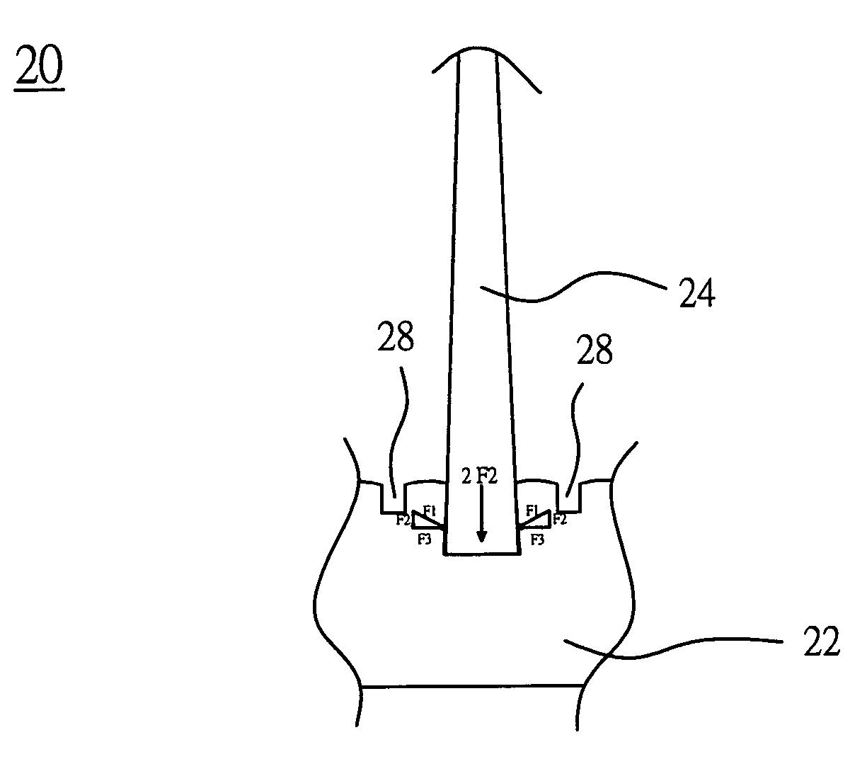
[0007] Hence, an object of the present invention is to provide a heat sink having heat-dissipating fins of non-uniform thickness, for making the heat-dissipating fins and the heat-dissipating base plate maintain tight contact after punching forming; increasing the contact area between the heat-dissipating fins and the heat-dissipating base plate; and effectively decreasing the conductive thermal resistance therebetween.
[0009] According to the heat sink of the present invention having heat-dissipating fins with non-uniform thickness, not only the tight contact between the heat-dissipating fins and the heat-dissipating base plate can be maintained after punching forming, but also the contact area therebetween can be increased so as to decrease the conductive thermal resistance and enhance the performance of the heat sink on dissipating heat.

Problems solved by technology

If the heat generated by the electronic device is not properly removed, the performance of the electronic device will be degraded, and what is worse, the electronic device may be burned.
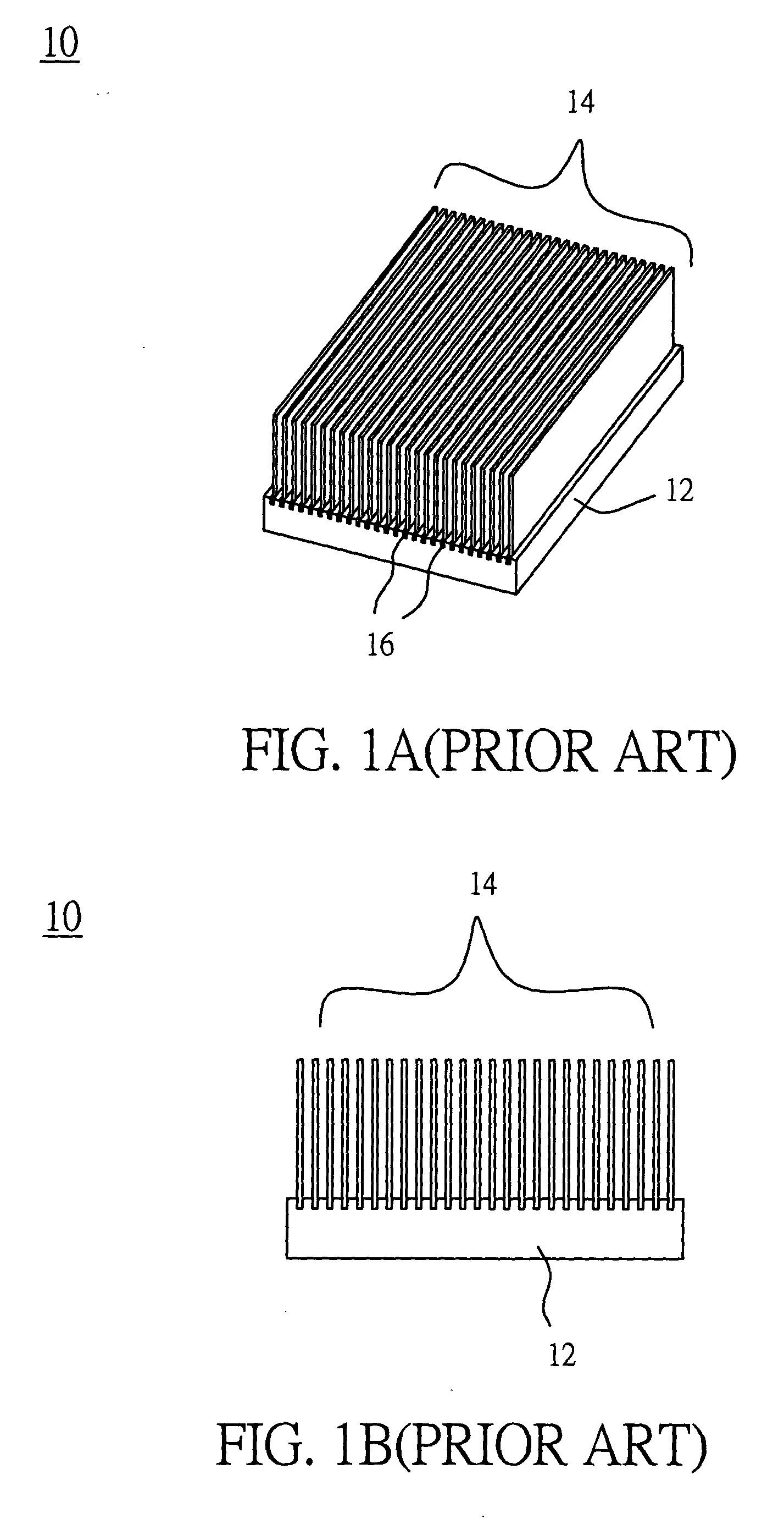
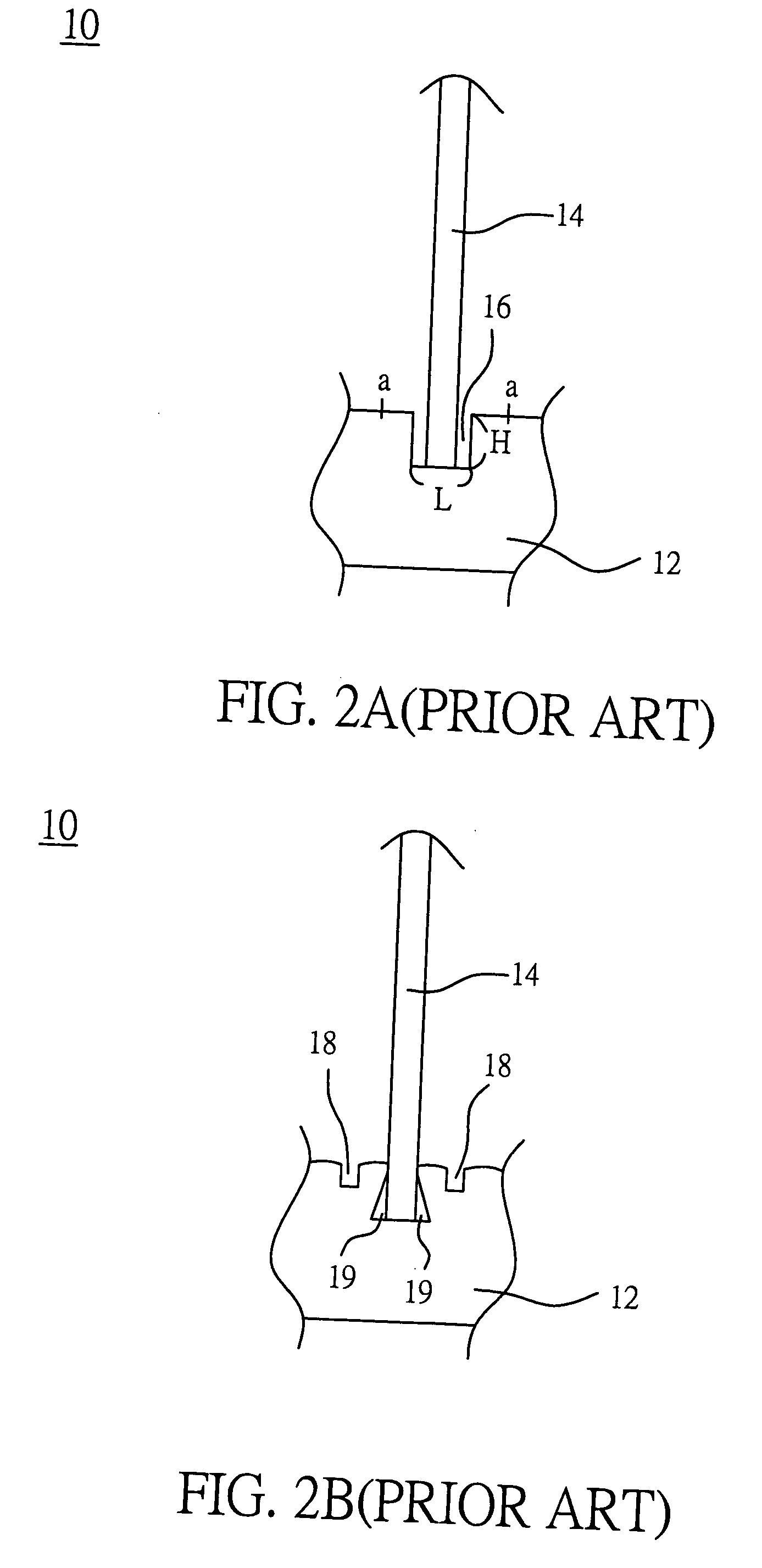
However, the height and thickness proportionality of heat-dissipating fins made by extrusion process are restricted by the current manufacturing techniques, and efficiency of heat-dissipating cannot be improved.
Thus, the requirement of dissipating the heat greatly increased by current electronic devices cannot be satisfied.
However, after welding, thermal conductive resistance is increased on the welding surface between heat-dissipating fins and the heat-dissipating base plate, so that the demand of high thermal conduction cannot be met.

Method used


Image

  • Heat dissipating fins of heat sink and manufacturing method thereof
  • Heat dissipating fins of heat sink and manufacturing method thereof
  • Heat dissipating fins of heat sink and manufacturing method thereof

Examples


Embodiment Construction

[0017] Please refer to FIG. 3A and FIG. 3B. FIG. 3A is a schematic diagram illustrating the structure of a heat sink 20 of the present invention. FIG. 3B is a front view of the heat sink 20 shown in FIG. 3A. Such as shown in FIG. 3A and FIG. 3B, the heat sink 20 of the present invention includes a heat-dissipating base plate 22 and a plurality of heat-dissipating fins 24. Since the heat-transfer property of copper is better, the heat-dissipating base plate 22 is made of the metal material selected from the group consisting of copper or copper alloys. A first surface of the heat-dissipating base plate 22 contacts with a heat source of which the heat is desired to be dissipated (not shown), and a plurality of grooves 26 with width L and depth H are formed on a second surface of the heat-dissipating base plate 22 by machining for inserting heat-dissipating fins 24. Furthermore, the heat-dissipating fins 24 are thin slices of the metal material selected from the group consisting of copp...


PUM


Abstract

A heat-dissipating fin of a heat sink for improving thermal conduction is disclosed. The heat sink has a base plate and a plurality of heat-dissipating fins. The base plate includes a first surface contacting with a heat source, and a second surface having a plurality of grooves orderly formed on the second surface. The heat dissipating fin of the heat sink has the feature that the thickness of the heat-dissipating fin is not uniform, and the thickness of a bottom surface of the heat-dissipating fin facing the groove is greater than the other portions of the heat-dissipating fin.

Description

FIELD OF THE INVENTION [0001] The present invention relates to a heat sink, and more particularly, to the heat sink of which heat-dissipating fins are not uniform in thickness. BACKGROUND OF THE INVENTION [0002] While the performance of an electronic device is enhanced, the heat-dissipating element or the heat-dissipating system has been an essential equipment in the current electronic devices. If the heat generated by the electronic device is not properly removed, the performance of the electronic device will be degraded, and what is worse, the electronic device may be burned. The heat-dissipating element is more important for micro electronic devices, such as integrated circuits, since with the increase of the component density and the improvement of the technology of packaging, the area of the integrated circuit decreases, and meanwhile, the heat in every unit square increases. Therefore, a rapid heat-dissipating element always plays an important role in electronic industrial fie...

Claims


Application Information

Patent Timeline
Patent Type & Authority Applications(United States)
IPC IPC(8): H05K7/20F28F3/02H01L21/48H01L23/36H01L23/367
CPCF28F3/02H01L21/4878H01L23/3672H01L2924/0002H01L2924/00
Inventor CHIEN, CHAO-NANHUANG, YU-HUNGCHEN, CHIN-MING
Owner DELTA ELECTRONICS INC
Learn More