
MRI method and apparatus with elimination of the ambiguity artifact

a magnetic resonance and artifact technology, applied in the field of magnetic resonance tomography, can solve the problems of non-existence of resonance condition during radio-frequency excitation by hf pulse, general unavoidable movement of anatomy, non-homogeneous boundary region, etc., and achieve the effect of avoiding the occurrence of ambiguity artifacts

Inactive Publication Date: 2005-01-06
SIEMENS AG
View PDF3 Cites 18 Cited by
  • Summary
  • Abstract
  • Description
  • Claims
  • Application Information

AI Technical Summary

Benefits of technology

[0015] An object of the present invention is thus to provide an imaging method for magnetic resonance tomography wherein the occurrence of the ambiguity artifact is avoided without impairing the measurement duration and the signal-to-noise ratio, not only when using spin-echo sequences but also when using GE sequences.
[0024] Advantageously, the two artifact-free images can be added together in order to compensate for the signal-to-noise loss.

Problems solved by technology

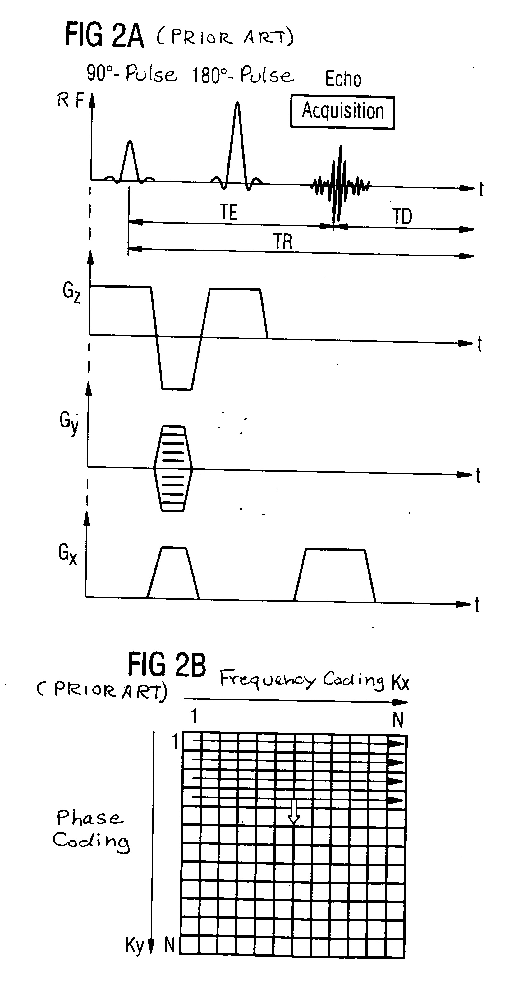
The scanning of the k-matrix (k-matrices in the case of data from multiple slices) typically requires, for spin-echo sequences with diagnostically usable image quality, several minutes of measurement time, which is a problem in many clinical applications.
In the case of examinations in the thorax or pelvic regions, movement of the anatomy is generally unavoidable (heart and respiratory movement, peristalsis).
In MRT imaging using spin-echo sequences as well as when using GE sequences, there is the general problem that the resonance condition during the radio-frequency excitation by the HF pulse exists not only in the field of view (FOV, characterized by homogeneity of the basic field as well as the gradient fields) but also in the non-homogeneous boundary region of the FOV.
This means that superimposed on the image of the actual measurement field is a generally disruptive image from the inhomogeneity region in the form of an artifact.

Method used


Image

  • MRI method and apparatus with elimination of the ambiguity artifact
  • MRI method and apparatus with elimination of the ambiguity artifact
  • MRI method and apparatus with elimination of the ambiguity artifact

Examples


Embodiment Construction

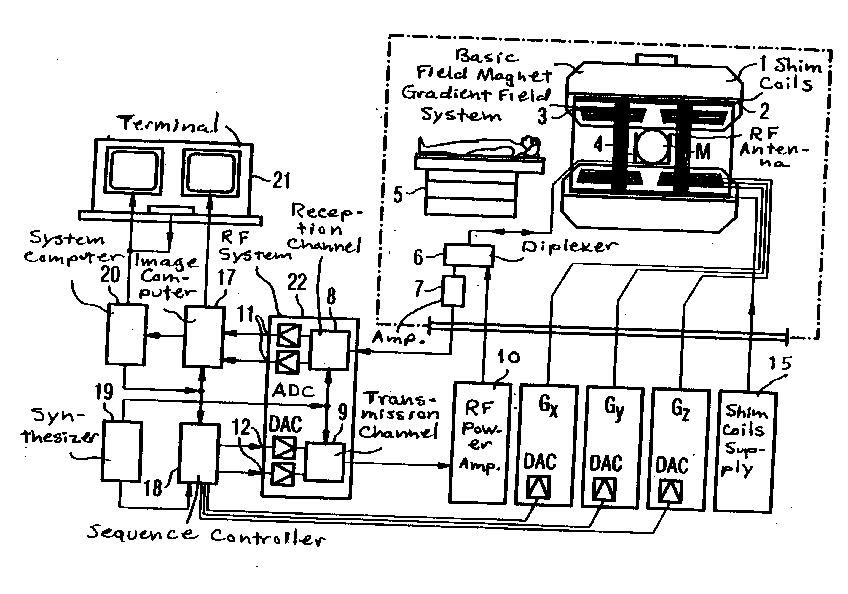
[0037]FIG. 1 schematically shows MRT apparatus for generating gradient pulses according to the prevent invention. The basic design of the nuclear spin tomography instrument corresponds here to the design of a conventional tomography apparatus with the exceptions described below. A basic field magnet 1 produces a strong magnetic field which is constant over time for polarization or alignment of the nuclear spins in the examination region of a subject, e.g., a part of a human body being examined. The high homogeneity of the basic magnetic field required for the magnetic resonance measurement is defined in a spherical measurement volume M into which the parts of the human body under examination are introduced. To support the homogeneity requirements and particularly to eliminate influences that are invariable over time, “shim plates” made of a ferromagnetic material are arranged at suitable locations. Influences that are variable over time are eliminated by shim coils 2 that are contro...


PUM


Abstract

In a method for magnetic resonance imaging, by combined switching of radio-frequency excitation pulses, slice selection gradient pulses, phase-coding gradient pulses and readout gradient pulses, a matrix in the k-space is scanned row-by-row and transformed using a Fourier transformation into a matrix in the spatial domain, with the polarity of the slice selection gradient being inverted during the scanning of the k-matrix, allowing elimination of the ambiguity artifact.

Description

BACKGROUND OF THE INVENTION [0001] 1. Field of the Invention [0002] The present invention relates in general to magnetic resonance tomography (MRT) as used in medicine for examining patients. The present invention relates in particular to a method for preventing the ambiguity artifact, particularly when using spin-echo sequences as well as when using gradient echo sequences, but without affecting the measurement duration and the signal-to-noise ratio. [0003] 2. Description of the Prior Art [0004] MRT is based on the physical phenomenon of nuclear magnetic resonance and has been successfully used as an imaging technique for more than 15 years in medicine and in biophysics. In this examination method, the subject is exposed to a strong, constant magnetic field. As a result, the nuclear spins of the atoms in the subject become aligned after having been previously randomly oriented. Radio-frequency energy can now excite these “ordered” nuclear spins to product a certain oscillation. In ...

Claims


Application Information

Patent Timeline
IPC IPC(8): G01R33/565
CPCG01R33/56563
Inventor KIEFER, BERTHOLD
Owner SIEMENS AG
Learn More