This helps you quickly interpret patents by identifying the three key elements:
Problems solved by technology
Method used
Benefits of technology
Benefits of technology
[0015] The invention is based on the recognition that a heatsink and a blower with an electric drive are provided in a single integrated apparatus for cooling of electronic components such as integrated semiconductorchip. The formation of a stator of the electric drive into the heatsink permits a significant simplification and reduction in size, which also provides for more uniform cooling of an electronic device, than has been achieved hitherto.
[0024] According to the present invention cooling air is introduced into the inlet, located above the heatsink, by means of a radial blower with blades located around the pins of the heatsink. This blower is driven by a brushless type DC electric drive that utilizes a ring typepermanent magnet rotor. This rotor has an opening in the center allowing for the transfer of incoming air to the center of the heatsink. When the electric current flows through the stator, the stator coils acquire a magnetic polarity. The poles of the magnetized rotor and stator coils attract and repel depending on the polarities. This action provides for a smooth continuous directional electric drive rotation.
Problems solved by technology
During normal operation many electronic components generate significant amounts of heat.
If this heat is not continuously removed the electronic component may overheat resulting in damage and / or a reduction in operating performance.
However, due to the weak airflow in the area adjacent to fan axle, the conditions for cooling the central part of the heatsink located underneath the fan are unfavorable.
In this case non-uniform cooling of the heatsink and electronic component will take place allowing for bad conditions for the heat exchange process.
However, placement of a centrifugal blower to the side of the heatsink increases the devices size and reduces its effectiveness.
This is because the location of the centrifugal blower leads to insufficient coordination between the direction of channel inlets and direction of airflow supplied from the blower.
The loss in airflow energy results in the reduction of airflow speed in the heat exchanging channels and the reduction of heat exchange efficiency.
Since this centrifugal fan operates by drawing air in through the heatsink, there is an area in the central part of the heatsink that receives poor air circulation.
This results in inefficient cooling of the heatsink's central surface area and uneven cooling of the heatsink in general.
To help correct this problem, one has to increase the fans power resulting in an increased airflow but not solving the initial problem.
In addition to the heat dissipation problems, the device is considerably larger due to the centrifugal fans placement above the heatsink.
Method used
Image
Click on the blue label to locate the original text in one second.
Reading with bidirectional positioning of images and text.
Examples
first embodiment
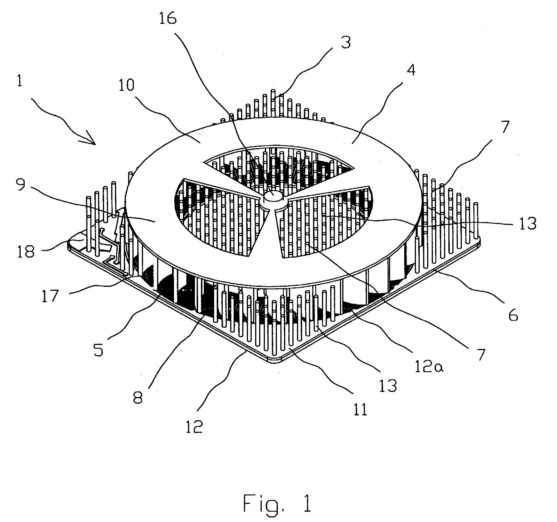
[0028]FIG. 1 is a perspective view showing the present invention;
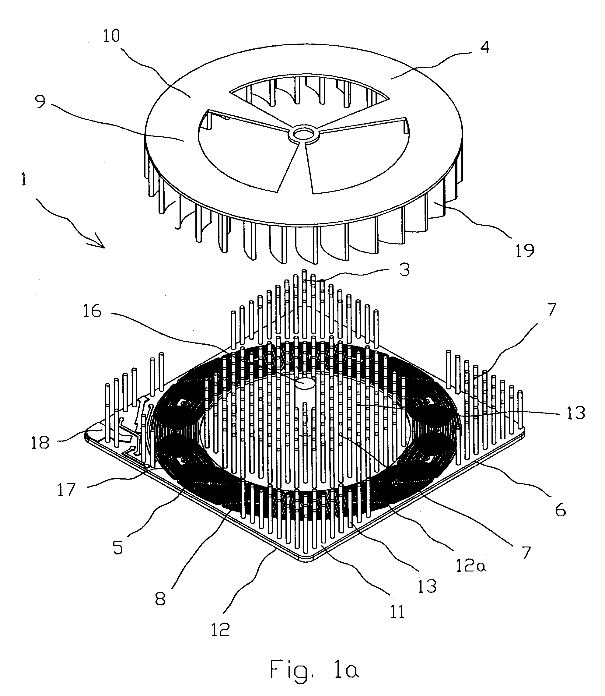
[0029]FIG. 1a is an exploded view showing a first embodiment of the present invention;
[0030]FIG. 2 is a top plan view of the apparatus in accordance with the present invention shown in FIG. 1;
[0031]FIG. 3 is a perspective view showing the embodiment of the present invention of FIG. 1 with a cover;
[0032]FIG. 4 is a perspective view showing the embodiment of the present invention of FIG. 1 with a cover and additional stator coils thereon;
[0033]FIG. 5 is a perspective view showing an embodiment of the present invention with a rotor of an electric drive removed from the apparatus;
[0034]FIG. 6 is a top plan view of the apparatus in accordance with the present invention shown in FIG. 5;
[0035]FIG. 7 is a perspective view showing the electric drive removed from the apparatus;
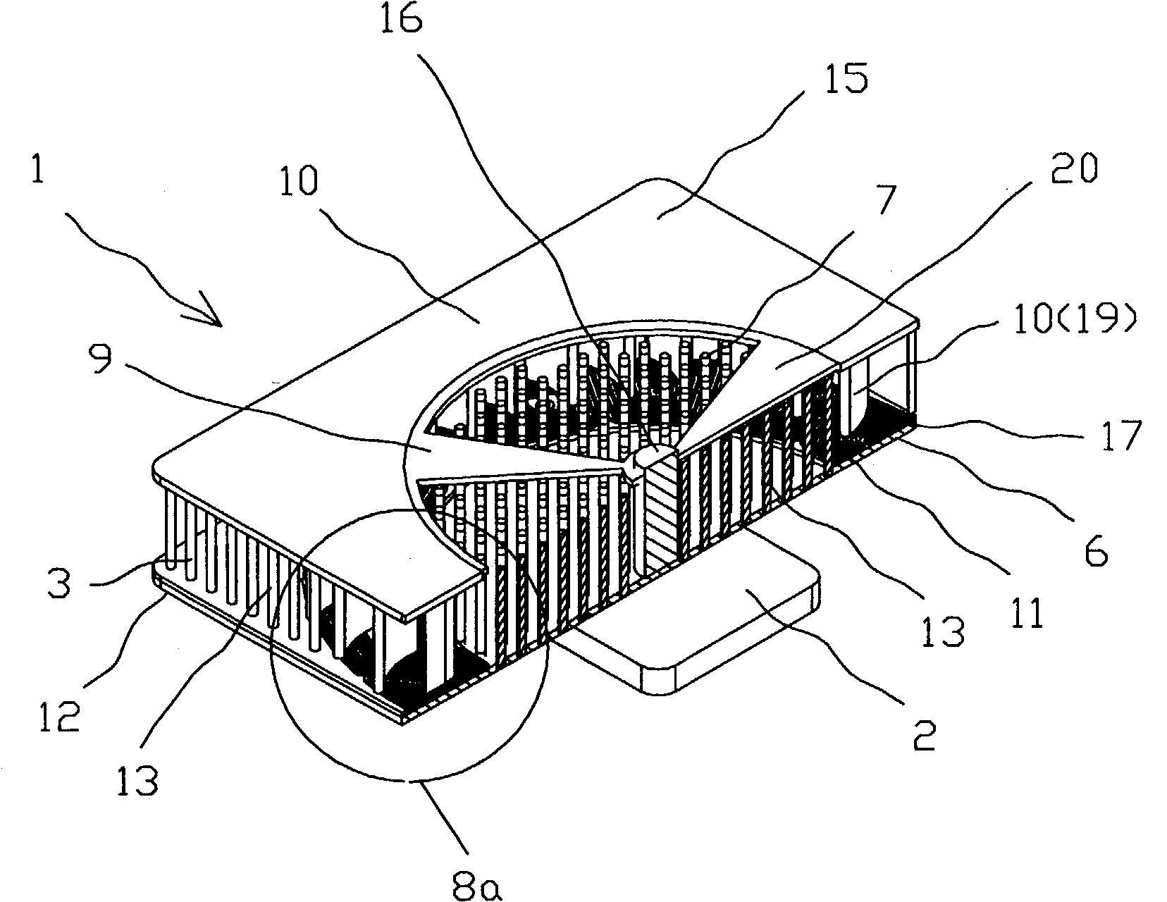
[0036]FIG. 8 is a half sectional view of the present invention shown in FIG. 3;
[0037]FIG. 8a is an enlarged perspective view of the part 8a shown ...
second embodiment
[0038]FIG. 9 is a perspective view showing the present invention;
[0039]FIG. 10 is a perspective view showing the embodiment of the present invention of FIG. 9 with the apparatus void of a cover;
[0040]FIG. 11 is a perspective view showing the embodiment of the present invention of FIG. 9 with the rotor of an electric drive removed from the apparatus;
[0041]FIG. 12 is a top plan view of the apparatus in accordance with the second embodiment of the present invention shown in FIG. 11.
DETAILED DESCRIPTION OF THE EMBODIMENTS
[0042] Two embodiments of the present invention will be described in detail below with reference to the accompanying drawings.
[0043]FIGS. 1-8, 8a show a first embodiment and FIGS. 9-12 show a second embodiment of the present invention.
[0044] An apparatus 1 (FIGS. 1-4) for cooling of the electronic component 2 (FIG. 8) comprises a heatsink 3, a blower 4 and an electric drive 5. The heatsink 3 (FIGS. 1, 3 and 5) has a base 6 on which a plurality of heat exchange mean...
PUM
Abstract
An apparatus for cooling of electronic components of the present invention are provided with a heatsink and a blower with an electric drive. The heatsink comprises a base and heat exchanging means. The electric drive comprises a stator and a rotor with an axle; the stator is rigidly built-in to the heatsink. The blower comprises a radial type magnetized impeller as the rotor. The base provides thermal contact with the electronic component and the heat exchanging means. The base is comprised of at least two layerscomposite material thereof including at least one layer of electrically insulating material and at least one layer of thermally and electrically conductive material that including the stator.
Description
CROSS REFERENCE TO RELATED APPLICATIONS [0001] The present application claims the benefit of priority of U.S. Provisional Patent Application Ser. No. 60 / 356,484, filed Feb. 13, 2002 for Edward Lopatinsky at al. the entire content of which is incorporated herein by reference.FIELD OF THE INVENTION [0002] The present invention relates generally to cooling devices and in particular, to cooling devices used for removing heat from electronic components by means of a gas flow, in particular air produced by a blower. BACKGROUND OF THE INVENTION [0003] During normal operation many electronic components generate significant amounts of heat. If this heat is not continuously removed the electronic component may overheat resulting in damage and / or a reduction in operating performance. In order to avoid such problems cooling devices are often used in conjunction with these components. [0004] One such cooling device is a fan assisted heatsink. In such a device a heatsink is formed from a material...
Claims
Application Information
Patent Timeline
Application Date:The date an application was filed.
Publication Date:The date a patent or application was officially published.
First Publication Date:The earliest publication date of a patent with the same application number.
Issue Date:Publication date of the patent grant document.
PCT Entry Date:The Entry date of PCT National Phase.
Estimated Expiry Date:The statutory expiry date of a patent right according to the Patent Law, and it is the longest term of protection that the patent right can achieve without the termination of the patent right due to other reasons(Term extension factor has been taken into account ).
Invalid Date:Actual expiry date is based on effective date or publication date of legal transaction data of invalid patent.
IPC IPC(8): H01L23/467H05K7/20
CPCH01L23/467H01L2924/0002H01L2924/00
InventorLOPATINSKY, EDWARDSCHAEFER, DANROSENFELD, SAVELIYFEDOSEYEV, LEV

