Form analysis to detect evoked response

Inactive Publication Date: 2005-01-06
MEDTRONIC INC
View PDF4 Cites 68 Cited by
  • Summary
  • Abstract
  • Description
  • Claims
  • Application Information

AI Technical Summary

Benefits of technology

[0009] The use of multiple morphology characteristics in determining the capture status may give more reliable results than the use of just one morphology characteristic. Accor

Problems solved by technology

It is often very difficult to distinguish an evoked response indicating CAP from post-pace sign

Method used


Image

  • Form analysis to detect evoked response
  • Form analysis to detect evoked response
  • Form analysis to detect evoked response

Examples


Embodiment Construction

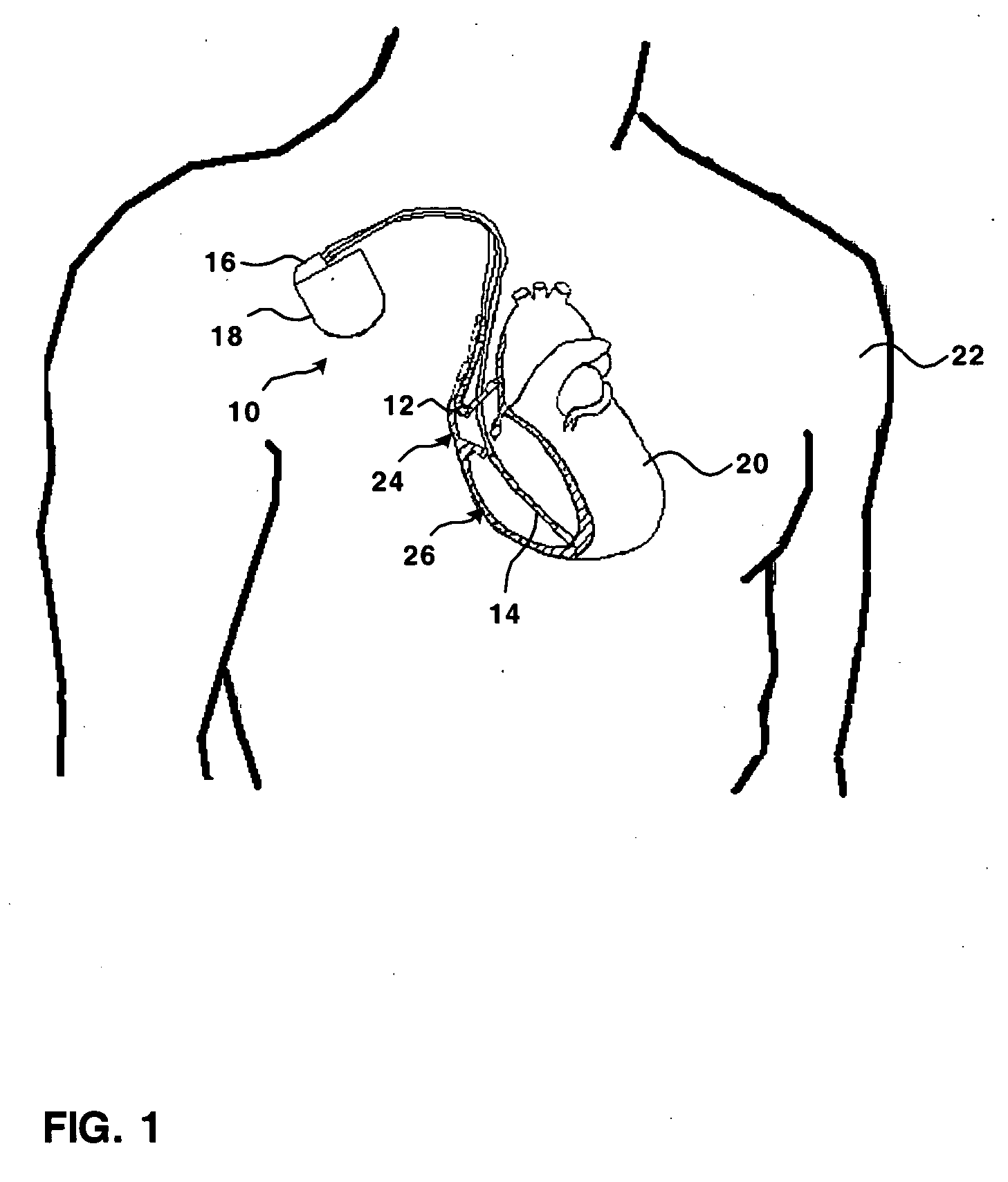
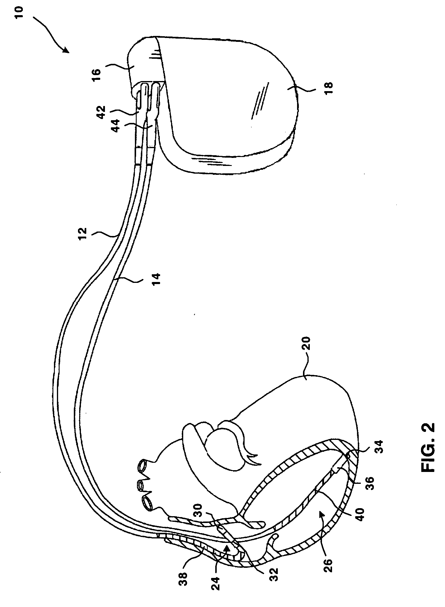
[0025]FIG. 1 is a schematic view of an exemplary implantable medical device (IMD) 10 implanted within a human patient 22. IMD 10 is an implantable pacemaker that may include cardioversion and defibrillation capability. The invention is not limited to the particular IMD shown in FIG. 1, however, but may be practiced by any number of implantable cardiac stimulation devices. The techniques of the invention may be practiced by a device that paces a single cardiac chamber or multiple chambers, that paces one or more atria and / or one or more ventricles, that includes or lacks cardioversion and defibrillation capability, and that paces in any pacing mode.

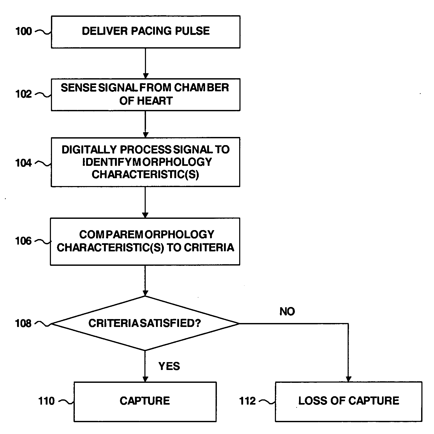
[0026] The invention is directed to techniques for determining capture status of a heart chamber that receives a pacing pulse from an implantable pulse generator incorporated in IMD 10. The capture status indicates whether the pacing pulse successfully captured the chamber of the heart to which the pacing pulse was applied. Accordingly, c...


PUM


Abstract

Method and device for determining capture status of a heart chamber that receives a pulse from an implantable pulse generator (IPG). Signal processing can be used to improve the reliability of capture detection by transforming the sensed response signal into a set of morphological characteristics. Analysis of selected morphological characteristics serves to distinguish signals indicative of capture from signals indicative of loss of capture.

Description

CROSS REFERENCE TO RELATED APPLICATION [0001] This application is a continuation-in-part of application Ser. No. 10 / 424,538, filed Apr. 25, 2003 (Attorney Docket No. P10670.00).FIELD OF THE INVENTION [0002] The invention relates to implantable medical devices having an implantable pulse generator (IPG) for cardiac stimulation, and more particularly, to detection of evoked response for capture management in an implantable medical device. BACKGROUND OF THE INVENTION [0003] An implantable medical device such as a cardiac pacemaker supplants some or all of the natural pacing function of a heart by delivering appropriately timed electrical stimulation signals designed to cause the myocardium of the heart to contract. An implantable pulse generator (IPG) in the device generates the electrical stimuli. To be effective, the stimuli should be of a sufficient strength (or amplitude) and duration (or pulse width) to cause the heart to beat, i.e., to “capture” the heart. A “capture threshold” o...

Claims


Application Information

Patent Timeline
IPC IPC(8): A61B5/0452A61N1/37
CPCA61N1/371A61B5/0452A61B5/349
Inventor SCHOLTEN, PATRICKDE BRUYN, HENRICUS W.M.OOSTERHOFF, PETERVAN OORT, GEESKE
Owner MEDTRONIC INC
Why Eureka
Try Eureka