
Private branch exchange back-up system, back-up device for private branch exchange and failure coping method of network system

a network system and private branch technology, applied in the field of private branch exchange backup system, backup device for private branch exchange and failure coping method of network system, can solve the problems of inability to control, inability to prevent continuation of normal operation of the ip terminal, and inability to control the ip terminal, so as to improve the reliability of operation.

Active Publication Date: 2005-01-06
NEC PLATFORMS LTD
View PDF14 Cites 6 Cited by
  • Summary
  • Abstract
  • Description
  • Claims
  • Application Information

AI Technical Summary

Benefits of technology

[0015] An object of the present invention is to provide a back-up device for an IP-PBX having improved operation reliability, an IP-PBX back-up system and a failure coping method of a network system.
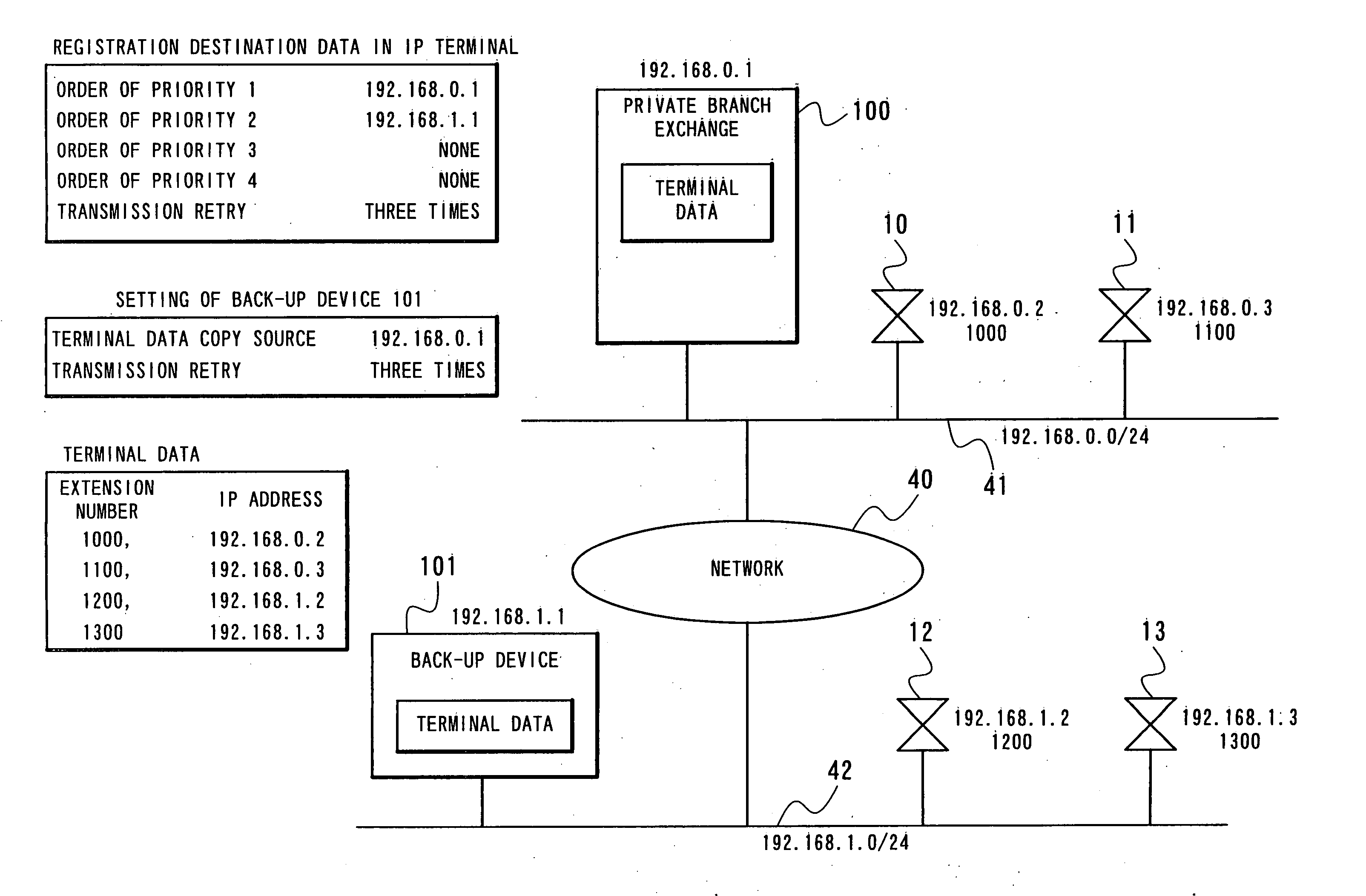
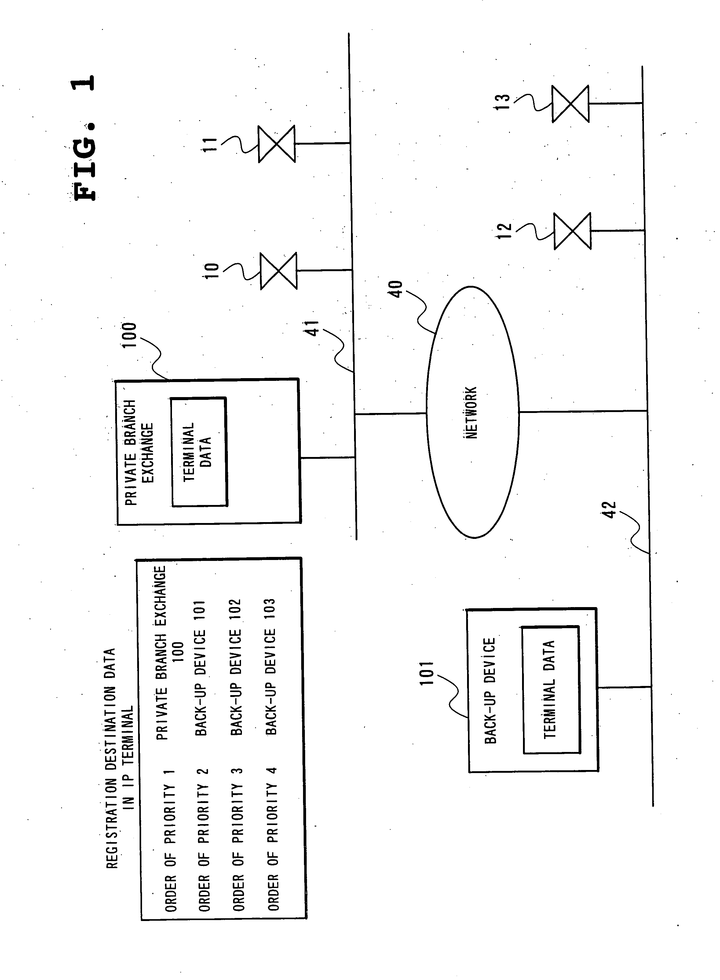
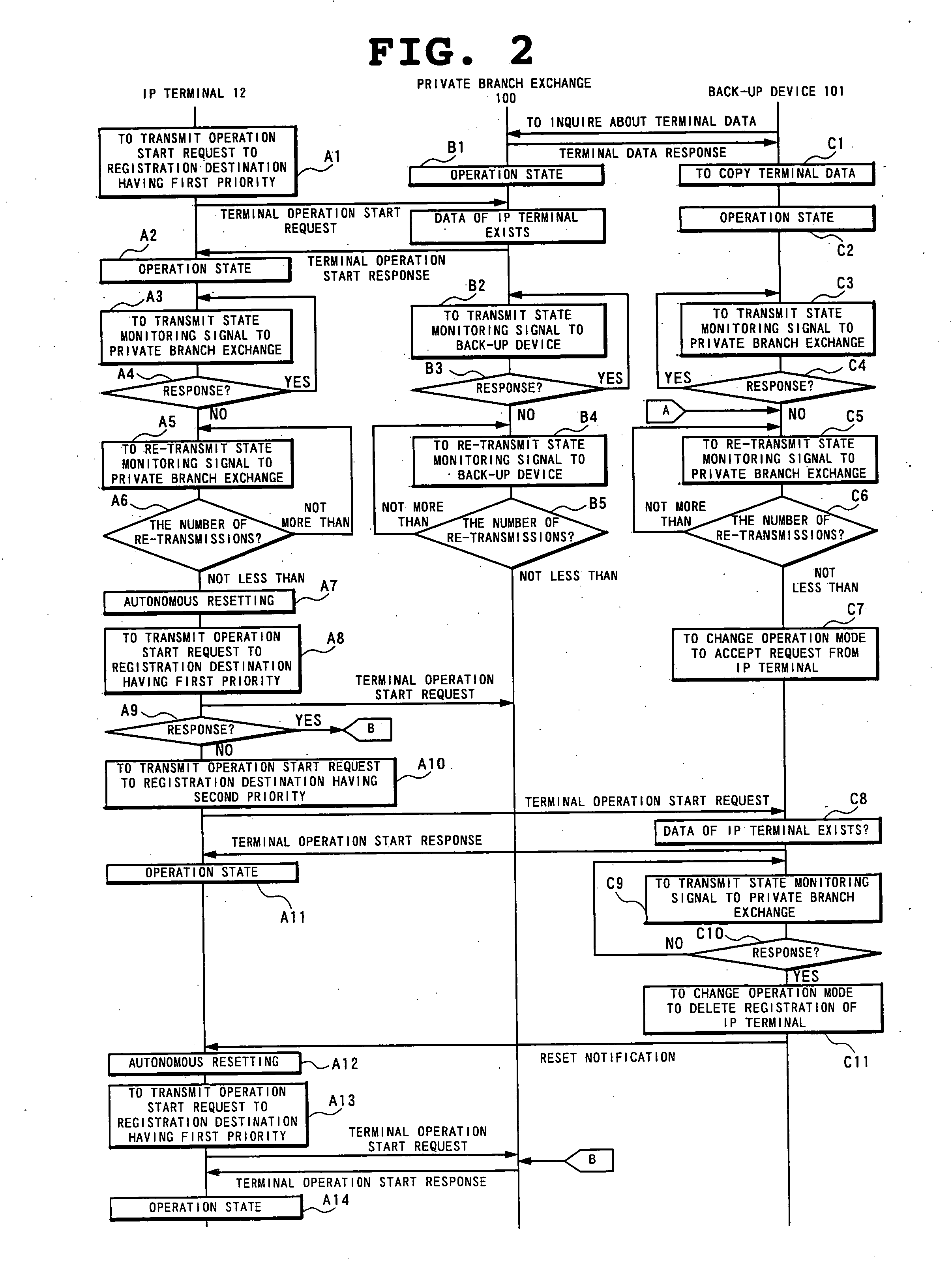
[0016] More specifically, the present invention provides a back-up device for an IP-PBX, an IP-PBX back-up system and a failure coping method of the system which, under the environment where an IP-PBX (hereinafter referred to as a private branch exchange) is used, when a local area network to which an IP extension multifunctional telephone (hereinafter referred to as an IP terminal) is connected, or an IP network (hereinafter referred to as a network) such as the Internet, or the private branch exchange itself develops a failure to disable control of the accommodated IP terminal, minimize stop time by temporarily shifting control of the IP terminal to the back-up device side to enable the IP terminal to resume operation.

Problems solved by technology

The first problem is that a failure occurring in a network such as a LAN or the Internet makes control of an IP terminal completely impossible to prevent continuation of normal operation of the IP terminal.
In particular, crucial is that not only a physical cable failure but also a software failure of a router might be a cause of impossible control.
As a result, control of the IP terminal is disabled.
In particular, when using a network to which unspecified numbers of apparatuses and networks are connected such as the Internet, reliability of each network can not be secured for sure.

Method used


Image

  • Private branch exchange back-up system, back-up device for private branch exchange and failure coping method of network system
  • Private branch exchange back-up system, back-up device for private branch exchange and failure coping method of network system
  • Private branch exchange back-up system, back-up device for private branch exchange and failure coping method of network system

Examples


second embodiment

[0090] Next, another embodiment of the present invention will be described in detail with reference to the drawings.

[0091]FIG. 4 is a diagram showing a network structure according to a second embodiment. With reference to FIG. 4, the present embodiment includes a private branch exchange 100, a back-up device 102 and IP terminals 10 and 11 connected to a network 41, the same network to which the private branch exchange 100 connects, a physically different network 42, and a back-up device 101 and IP terminals 12 and 13 connected to the network 42.

[0092] In the structure example shown in FIG. 1, when the private branch exchange 100 itself develops a failure, the IP terminals 12 and 13 go under the control of the back-up device 101 to continue operation. As to the IP terminals 10 and 11, however, no device for controlling the same exists, so that until the failure of the,private branch exchange 100 is recovered, they are not allowed to operate. With the structure shown in FIG. 4, when...

third embodiment

[0095] Next, third embodiment of the present invention will be described in detail with reference to the drawings.

[0096] With reference to FIG. 5, the present embodiment includes, in addition to the components in the structure example shown in FIG. 1, gateway devices 20 and 21 connected as connection units from an IP network to a public switched telephone network. The gateway devices 20 and 21, similarly to the IP terminals 12 and 13, ordinarily transmit and receive a terminal operation start request to / from the private branch exchange 100 to conduct arrival call processing between the IP network and the public switched telephone network under the control of the private branch exchange 100.

[0097] When transmission / reception of a state monitoring signal is cut off between the private branch exchange 100 and the back-up device 101, the back-up device 101 changes an operation mode of its own device to accept a terminal operation start request from the IP terminals 12 and 13. The devi...

fourth embodiment

[0102] Next, a fourth embodiment of the present invention will be described in detail with reference to the drawings.

[0103] With reference to FIG. 6, the present embodiment includes a network 41, a private branch exchange 100 connected to the network 41, physically different networks 40 and 42, and back-up devices 101 and 102 and IP terminals 12 and 13 connected to the network 42. The IP terminals 12 and 13 store such registration destination data as shown in FIG. 6. With this structure, when the network 40 or the private branch exchange 100 develops a failure, the IP terminals 12 and 13 go under the control of the back-up device 101 to enter the operation state, while when the back-up device 101 develops a failure, the terminals transmit a terminal operation start request to the further subsequent back-up device 102 to go under the control of the back-up device 102, so that they are allowed to continue operation.

[0104] As compared with the above-described Literature 1 and Literat...


PUM


Abstract

The back-up device for an IP-PBX of the present invention is connected to each network. The private branch exchange is connected to an individual network to manage and hold the entire terminal device. The back-up device holds each terminal data of a group of terminal devices in a connected network. As a result, when connection management by the private branch exchange develops a failure, the back-up device secures connection management in the network to which the back-up device is connected. When the network or the private branch exchange itself develops a failure to disable control of an accommodated IP terminal, this arrangement enables the IP terminal to resume operation by temporarily shifting control of the IP terminal to the back-up device side, thereby minimizing stop time.

Description

BACKGROUND OF THE INVENTION [0001] 1. Field of the Invention [0002] The present invention relates to a back-up device for an IP-PBX (Internet Protocol-Private Branch Exchange) targeting a failure of an IP-PBX, an IP-PBX back-up system and a failure coping method of a system. [0003] 2. Description of the Related Art [0004] Conventional back-up device for IP-PBX is in general equipped with a back-up device for the purpose of coping with physically different networks. Such a conventional IP-PBX system as shown in FIG. 7, for example, includes physically different networks 41 and 42, a network 40 connecting the networks, an IP-PBX device (hereinafter referred to as a private branch exchange or a private branch exchange 100) and IP terminals 10 and 11 connected to the network 41, and IP terminals 12 and 13 connected to the network 42 (see e.g. Japanese Patent Laying-Open (Kokai) No. Showa 63-285053 which will be referred to as Literature 1 hereinafter). [0005] Thus structured conventiona...

Claims


Application Information

Patent Timeline
IPC IPC(8): H04L45/586H04M3/00H04M3/22H04M7/00H04Q3/00H04Q3/58H04Q3/62
CPCH04M3/22H04M3/42314H04M7/00H04M7/006Y10S707/99953H04Q3/62H04Q2213/13167H04Q2213/1322H04Q2213/13389H04Q3/0062
Inventor SUZUKI, YASUNORI
Owner NEC PLATFORMS LTD
Learn More