Electrical fan system for vehicle
a technology of electric fan and electric motor, which is applied in the direction of domestic cooling equipment, lighting and heating equipment, instruments, etc., can solve the problems of large rated capacity, increased weight, and poor distribution of air blown to the radiator, so as to reduce the increase of cost, reduce wear and tear, and increase the life
- Summary
- Abstract
- Description
- Claims
- Application Information
AI Technical Summary
Benefits of technology
Problems solved by technology
Method used
Image

Examples
first embodiment
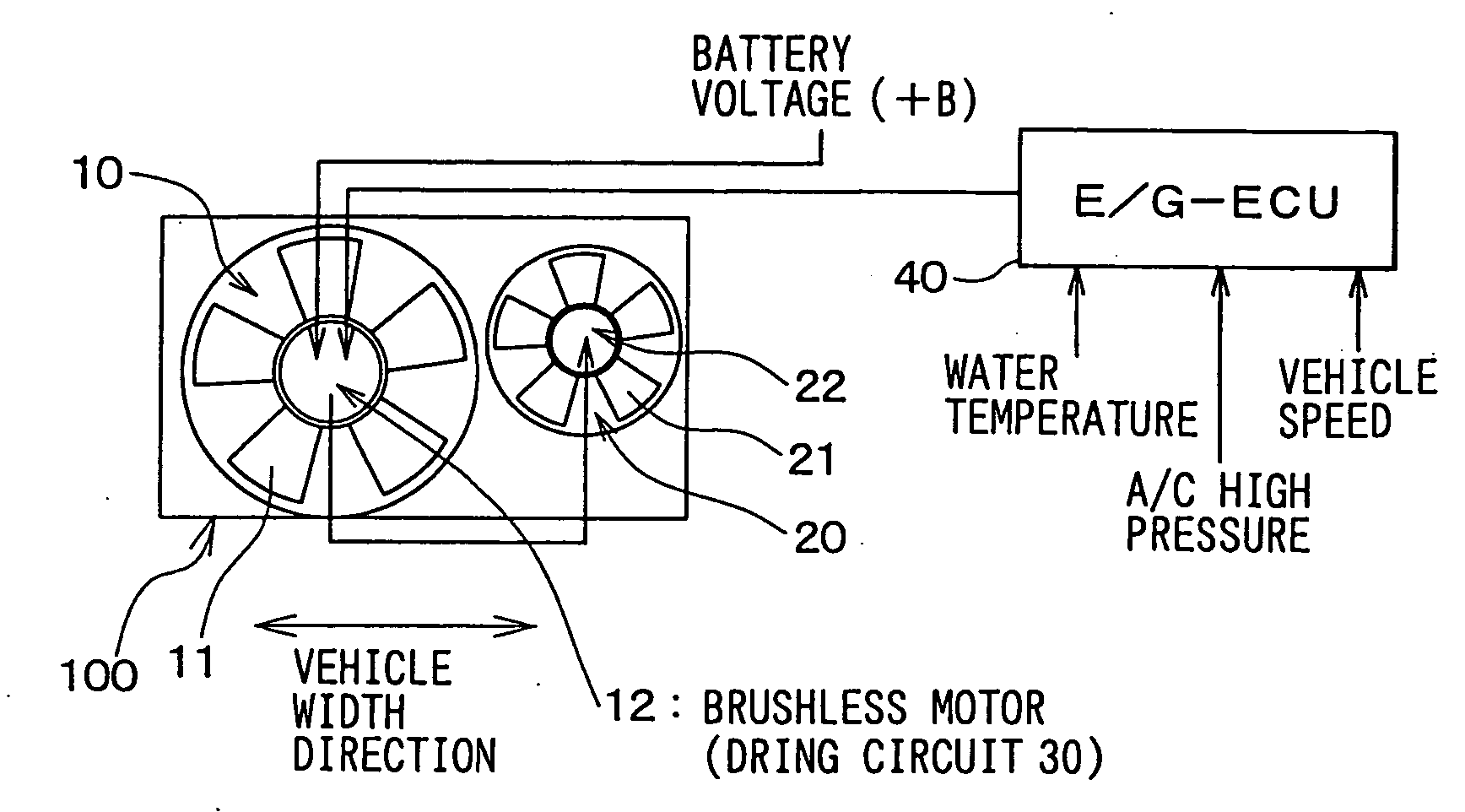
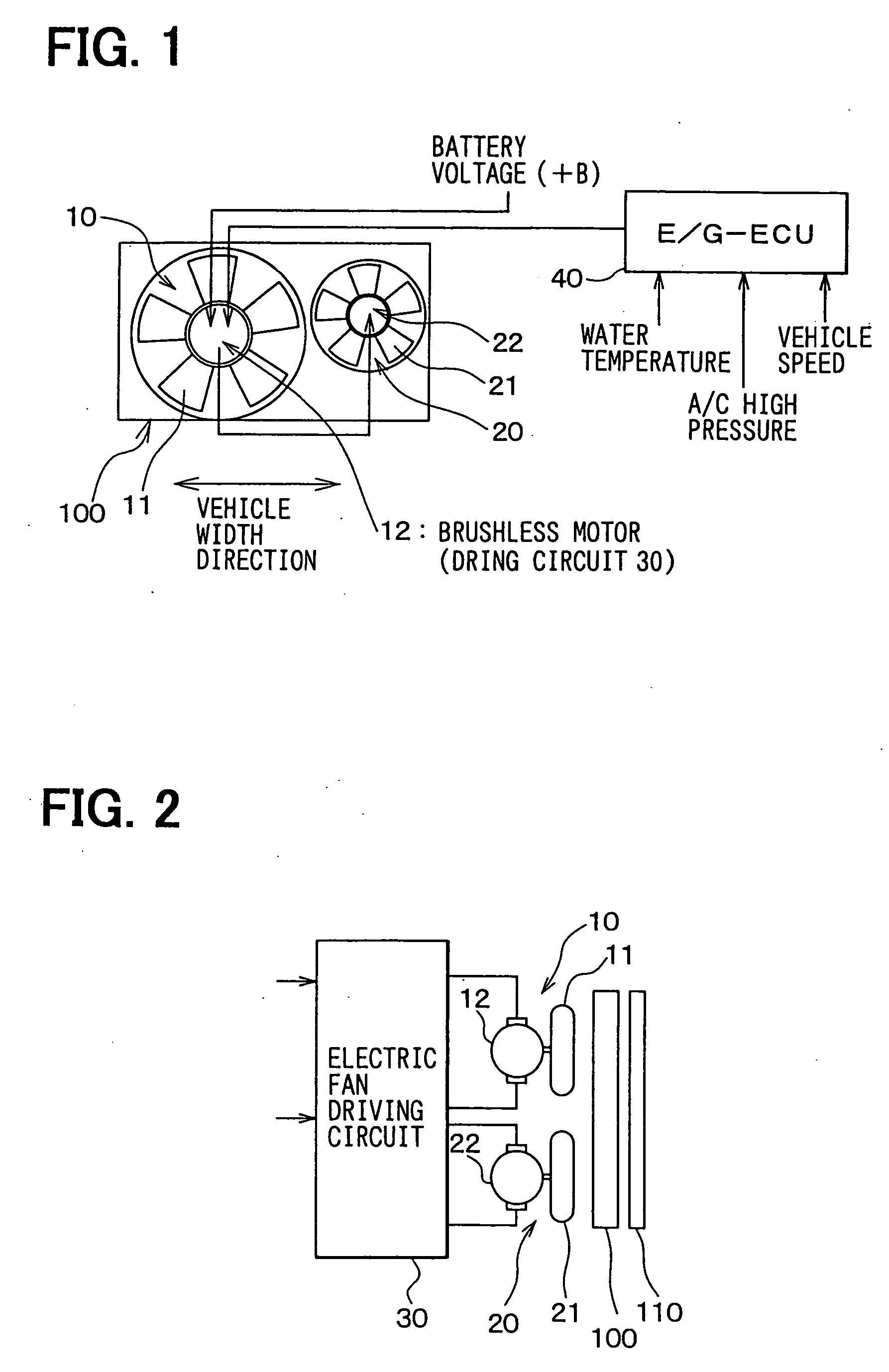
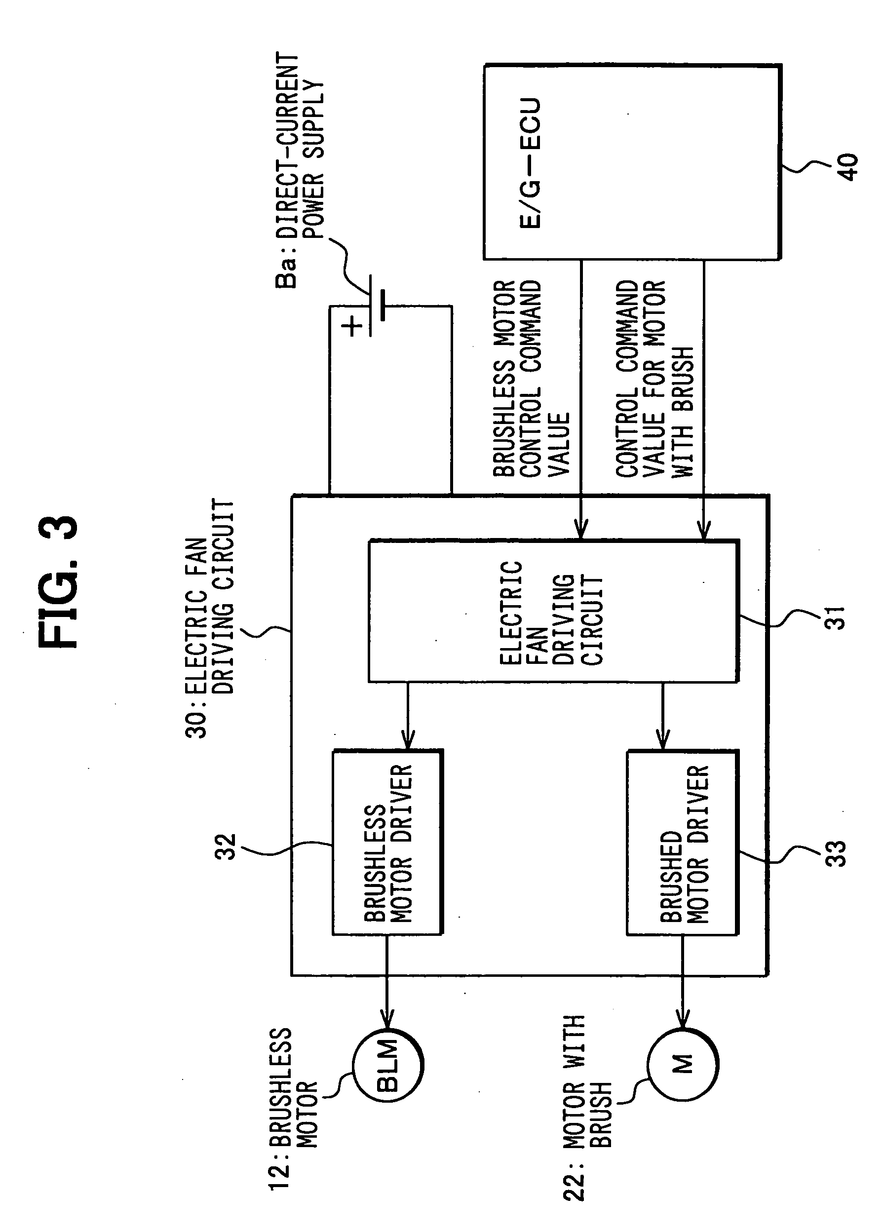
[0034]FIGS. 1 through 4 depict configurations of an electric fan system for a vehicle 120 (FIG. 10) according to a first preferred embodiment of the present invention. FIGS. 1 and 2 are schematic views showing the configuration of the electric fan system for a vehicle. The electric fan system for a vehicle has, as shown in FIG. 1, electric blowers 10, 20 within the engine compartment of a vehicle. The electric blower 10 has an impeller 11 and a brushless motor 12 for rotationally driving the impeller 11, and the electric blower 20 has an impeller 21 and a brushed motor (direct-current “DC” motor) 22 for rotationally driving the impeller 21. Here, the electric blowers 10, 20 serve to distribute cooling air to a radiator 100 and a condenser 110 for cooling the radiator 100 and the condenser 110.
[0035] The radiator 100 and the condenser 110 are disposed within the engine compartment along the longitudinal direction of the vehicle. The radiator 100 cools cooling water (engine cooling w...
second embodiment
[0053] In relation to the first embodiment described above, there has been disclosed an example in which the brushed motor 22 is activated in addition to the brushless motor 12 only when it is determined that the cooling water temperature is equal to or higher than a predetermined value. However, the present invention is not limited to this example, and it is also possible that the brushed motor 22 is activated in addition to the brushless motor 12 only when it is determined that the increased rate of the cooling water temperature is equal to or higher than a predetermined value.
[0054] Specifically, a second preferred embodiment relates to a vehicular electric fan system that distributes cooling air to a radiator 100 for cooling cooling water circulated in a vehicular water-cooled engine 135 and a condenser 110 for cooling a refrigerant circulated within an automobile air conditioner. The electric fan system has an electric blower 10 for distributing the cooling air to the radiator...
third embodiment
[0061] In relation to the above-described embodiments, explanation has been made about an example in which the brushed motor 22 is activated in addition to the brushless motor 12 when it is determined that the temperature of the cooling water (or the increase rate of the temperature) is equal to or higher than a predetermined value, or when it is determined that the refrigerant pressure (or the increase rate of the pressure) in the condenser is equal to or higher than a predetermined value. However, even under such conditions, the brushed motor 22 may remain inactive provided that the travel speed of the vehicle is equal to or higher than a predetermined speed.
[0062] Operation of this embodiment will now be described using FIG. 9. Note that like reference numerals are used for those operations that are similar to the first embodiment and therefore, detailed explanations that are repetitive will be omitted.
[0063] Specifically, in step S100A, a vehicle speed V detected by a vehicle ...
PUM
 Abstract
Description
Claims
Application Information
 - R&D
- Intellectual Property
- Life Sciences
- Materials
- Tech Scout
- Unparalleled Data Quality
- Higher Quality Content
- 60% Fewer Hallucinations
Browse by: Latest US Patents, China's latest patents, Technical Efficacy Thesaurus, Application Domain, Technology Topic, Popular Technical Reports.
© 2025 PatSnap. All rights reserved.Legal|Privacy policy|Modern Slavery Act Transparency Statement|Sitemap|About US| Contact US: help@patsnap.com