Method and apparatus for adjustably inducing biaxial strain

a technology of inducing strain and biaxial strain, which is applied in the direction of simultaneous indication of multiple variables, instruments, machines/engines, etc., can solve the problems of not generating strain and stress, difficult to apply direct to films, and difficult to install complex bulge test apparatuses inside the five cubic millimeter volume and vacuum environment. achieve the effect of reducing the diameter of the tub

Inactive Publication Date: 2005-01-13
RGT UNIV OF CALIFORNIA
View PDF14 Cites 4 Cited by
  • Summary
  • Abstract
  • Description
  • Claims
  • Application Information

AI Technical Summary

Problems solved by technology

Such techniques present challenging problems because bulk methods such as uniaxial tension testing, are very difficult to apply directly to films.
Difficulties include generating forces and strains required in a small space, gripping the film, and prevention of bending force components in the film.
While micro-electromechanical uniaxial strain fixtures have been fabricated, the approach does not generate the state of strains and stresses seen in chemical and biological micro-sensors, micro-actuators, passivation layers, micro-electronics, data storage and other film-based devices.
In addition, it is infeasible to install the complex bulge test apparatus inside the five cubic millimeter volume and vacuum environment of a Transmission Electron Microscope (TEM) objective lens.
Inducing radial strain through direct thermal expansion for observation of a thin film by a TEM is infeasible.

Method used


Image

  • Method and apparatus for adjustably inducing biaxial strain
  • Method and apparatus for adjustably inducing biaxial strain
  • Method and apparatus for adjustably inducing biaxial strain

Examples


Embodiment Construction

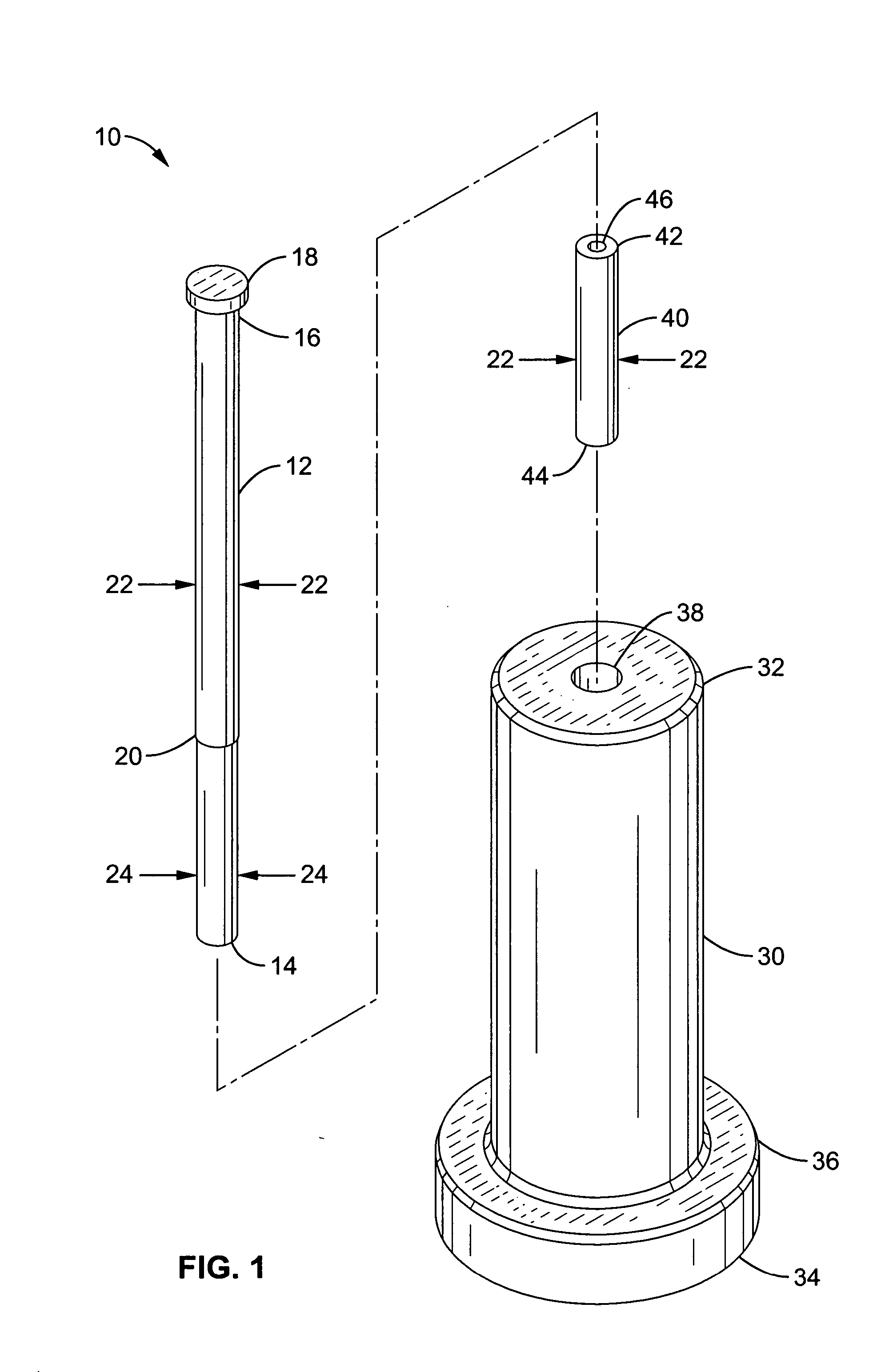
[0056] Referring more specifically to the drawings, for illustrative purposes the present invention is embodied in the apparatus generally shown in FIG. 1 through FIG. 10. It will be appreciated that the apparatus may vary as to configuration and as to details of the parts, and that the method may vary as to the specific steps and sequence, without departing from the basic concepts as disclosed herein.

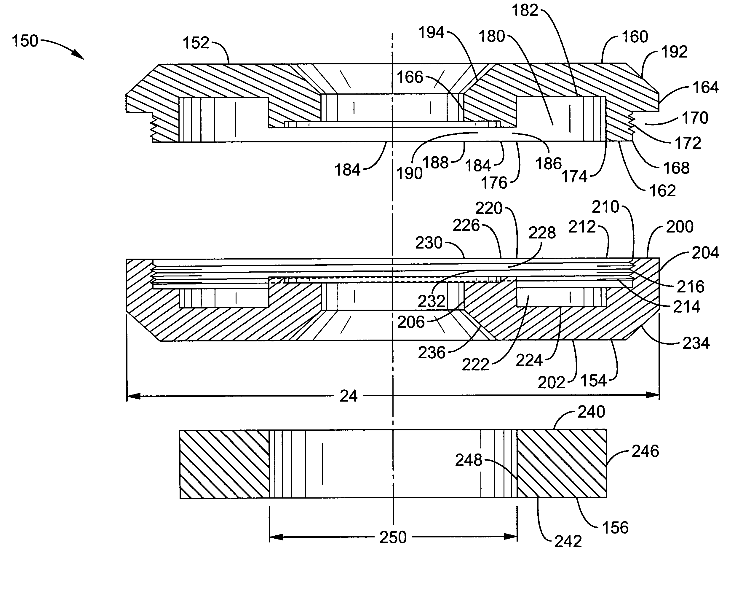
[0057] In the context of this invention, a ring of shape memory alloy has an outer perimeter and an inner perimeter. A change in perimeter can be a change in the size of the perimeter, a change in the shape of the perimeter, or both. For example, reducing the inner diameter of a circular ring changes its inner diameter and inner perimeter. Changing a circular ring to an oval ring changes the shape of its inner perimeter and may or may not change the size of its inner perimeter. References to a change in diameter are synonymous with a change in perimeter.

[0058]FIG. 1 illustrates a pla...


PUM


Abstract

An apparatus comprising a shape memory alloy is configured as a ring shaped sample holder for a transmission electron microscope and imparts uniform biaxial strain on a thin film mounted within. The sample holder responds to a change in temperature by changing the inner diameter, which imparts biaxial strain. In other embodiments, the sample holder is configured to change the inner diameter and change the strain on a thin film reversibly and repeatedly. In further embodiments, the sample holder is non circular. In still further embodiments, the apparatus is configured as a prime mover of a reversible radial actuator. Methods for making and using the apparatus are included in other embodiments.

Description

CROSS-REFERENCE TO RELATED APPLICATIONS [0001] This application claims priority from U.S. provisional application Ser. No. 60 / 467,163 filed on Apr. 30, 2003, incorporated herein by reference in its entirety.STATEMENT REGARDING FEDERALLY SPONSORED RESEARCH OR DEVELOPMENT [0002] This invention was made with Government support under Grant No. DE-AC03-76SF00098, awarded by the Department of Energy. The Government has certain rights in this invention.INCORPORATION-BY-REFERENCE OF MATERIAL SUBMITTED ON A COMPACT DISC [0003] Not Applicable NOTICE OF MATERIAL SUBJECT TO COPYRIGHT PROTECTION [0004] A portion of the material in this patent document is subject to copyright protection under the copyright laws of the United States and of other countries. The owner of the copyright rights has no objection to the facsimile reproduction by anyone of the patent document or the patent disclosure, as it appears in the United States Patent and Trademark Office publicly available file or records, but ot...

Claims


Application Information

Patent Timeline
Patent Type & Authority Applications(United States)
IPC IPC(8): F03G7/06
CPCF03G7/065
Inventor VESTEL, MICHAEL J.OSHATZ, DARYL PATRICK
Owner RGT UNIV OF CALIFORNIA
Why Eureka
Try Eureka