
Method to fabricate asymmetric wrinkles using biaxial strains

a technology of asymmetric wrinkles and strains, applied in the direction of vacuum evaporation coatings, chemical vapor deposition coatings, coatings, etc., can solve the problems of limited ability of current tensile stages to provide, lack of flexibility, and limited practicability of this process, so as to reduce the size of the stage, maintain structural rigidity, and quick and accurate registration

Active Publication Date: 2017-04-06
SAHA SOURABH KUMAR
View PDF2 Cites 2 Cited by
  • Summary
  • Abstract
  • Description
  • Claims
  • Application Information

AI Technical Summary

Benefits of technology

Enables the fabrication and tuning of complex micro and nano scale patterns, reducing manufacturing costs by a factor of at least 10 and accessing previously unexplored design spaces for wrinkle patterns, including asymmetric 2-D modes not accessible via equibiaxial strains.

Problems solved by technology

However, practical import of this process is limited by the lack of flexibility, i,e., due to the inability to fabricate a variety of complex 2-D patterns.
This is due to the limited ability of current tensile stages to provide the means to apply large, accurate, and / or non-equibiaxial strains within a small footprint.
In such systems, the state of pure compression becomes unstable beyond a critical strain and wrinkles are formed via periodic bending of the film / base.
Although current techniques and models are a valuable toolkit for predictive design and fabrication of wrinkled patterns, they are still inadequate in satisfying the need for a variety of different complex patterns.
The set of wrinkle patterns that can be fabricated is limited by the achievable range and types of compressive strains.
Due to this, exploring the design space for large uniaxial or non-equibiaxial strains becomes a material selection problem.
However, existing biaxial mechanical stages are often too large to use within vacuum chamber based equipment that are necessary for generation of thin films during wrinkle fabrication.

Method used


Image

  • Method to fabricate asymmetric wrinkles using biaxial strains
  • Method to fabricate asymmetric wrinkles using biaxial strains
  • Method to fabricate asymmetric wrinkles using biaxial strains

Examples


Embodiment Construction

[0017]To enable the fabrication and tuning of wrinkle patterns, one must solve these sub-problems: (i) fabrication of a bilayer system with the desired material properties and geometry, (ii) compression of the top stiff film, and (iii) in-situ visualization of pattern formation.

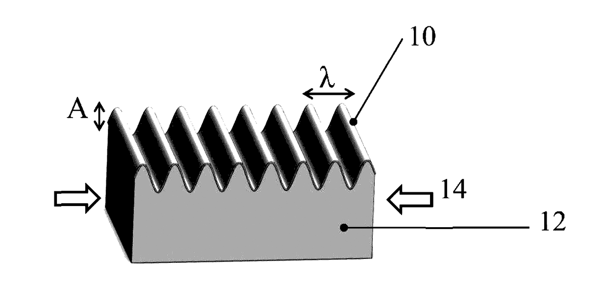
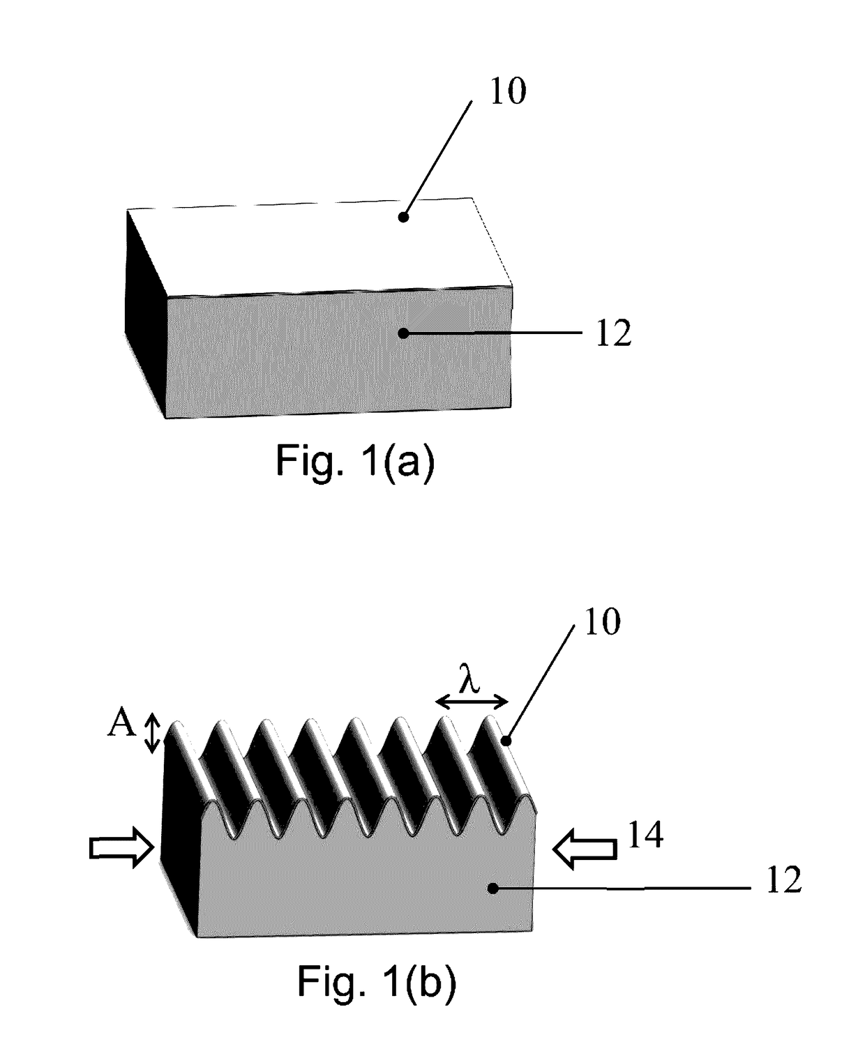
[0018]Stretchable bilayers with large stiffness ratio can be fabricated by attaching or growing a thin stiff film 10 on top of a thick elastomeric base 12. For example, exposing a polydimethylsiloxane (PDMS) film to air or oxygen plasma leads to the formation of a thin glassy layer on top of the exposed PDMS surface via oxidation. Alternatively, a metallic or polymeric thin film may be deposited on top of PDMS to obtain the desired bilayer. The top layer thickness can be tuned by controlling the duration of plasma oxidation or the deposition process; whereas the stiffness ratio may be tuned by selecting the appropriate top / bottom materials. The preferred embodiment of the stage can be used with both plasma ox...


PUM

PropertyMeasurementUnit
widthaaaaaaaaaa
widthaaaaaaaaaa
widthaaaaaaaaaa

Abstract

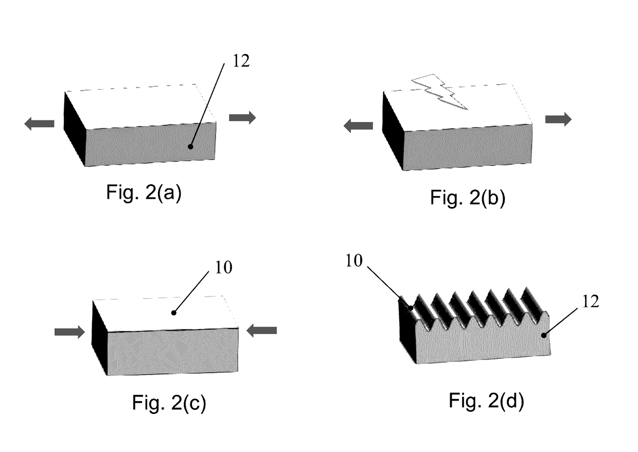
Wrinkling of supported thin films is a strain-driven phenomenon that enables scalable and low-cost fabrication of periodic micro and nano scale structures. The morphology of wrinkles depends on both the magnitude and the nature of compressive strains that are applied to the thin film. This disclosure presents the methods to fabricate asymmetric 2-D wrinkled structures using biaxial compressive strains. The method relies on the dependence of wrinkle morphology on both strains and strain paths to generate asymmetric 2D wrinkles. Asymmetry is achieved by deliberately traversing the system through a strain state that creates cracks along a preferential direction. Fabricated patterns include non-uniform zigzag wrinkles that demonstrate period doubling only along one direction.

Description

RELATED APPLICATIONS[0001]This application is a divisional of U.S. application Ser. No. 14 / 590,448 filed on Jan. 6, 2015; this application also claims the benefit of U.S. Provisional Application No. 61 / 923,912 filed on Jan. 6, 2014. The entire contents of both of these applications are incorporated herein by reference.BACKGROUND OF THE INVENTION[0002]This divisional application relates to methods of fabricating asymmetric 2-D wrinkle that are formed via compressive biaxial strains in bilayer composite materials and more particularly to methods of fabricating physical micro and nano scale structures that are generated upon compression of thin films.[0003]Wrinkling is a strain-driven self-organization phenomenon that is commonly observed in natural systems over a wide length scale. Recently, this phenomenon has been incorporated into engineered systems to generate micro and nano scale patterns. For example, wrinkling of bilayer materials has been used to fabricate periodic sinusoidal ...

Claims


Application Information

Patent Timeline
Patent Type & Authority Applications(United States)
IPC IPC(8): B29C55/16B29C55/20C23C16/06B29C37/00C23C14/20B29C55/02B29C55/00
CPCB29C55/16B29C55/023B29C55/20B29C55/005B29L2009/008C23C14/20C23C16/06B29K2083/00B29C37/0025B29C55/12
Inventor SAHA, SOURABH KUMAR
Owner SAHA SOURABH KUMAR
Learn More