Gear-shifting device for manual transmission

Inactive Publication Date: 2005-01-13
HONDA MOTOR CO LTD
View PDF4 Cites 18 Cited by
  • Summary
  • Abstract
  • Description
  • Claims
  • Application Information

AI Technical Summary

Benefits of technology

[0011] In consideration of the above mentioned problems, it is an object of the present invention to provide a gear-shifting device for a manual transmission, whic

Problems solved by technology

However, the increase of the leverage of the system transmitting the operational force from the change-lever to the synchro-sleeve also increases the stroke of the change-lever.
In this respect, such

Method used


Image

  • Gear-shifting device for manual transmission
  • Gear-shifting device for manual transmission
  • Gear-shifting device for manual transmission

Examples


Embodiment Construction

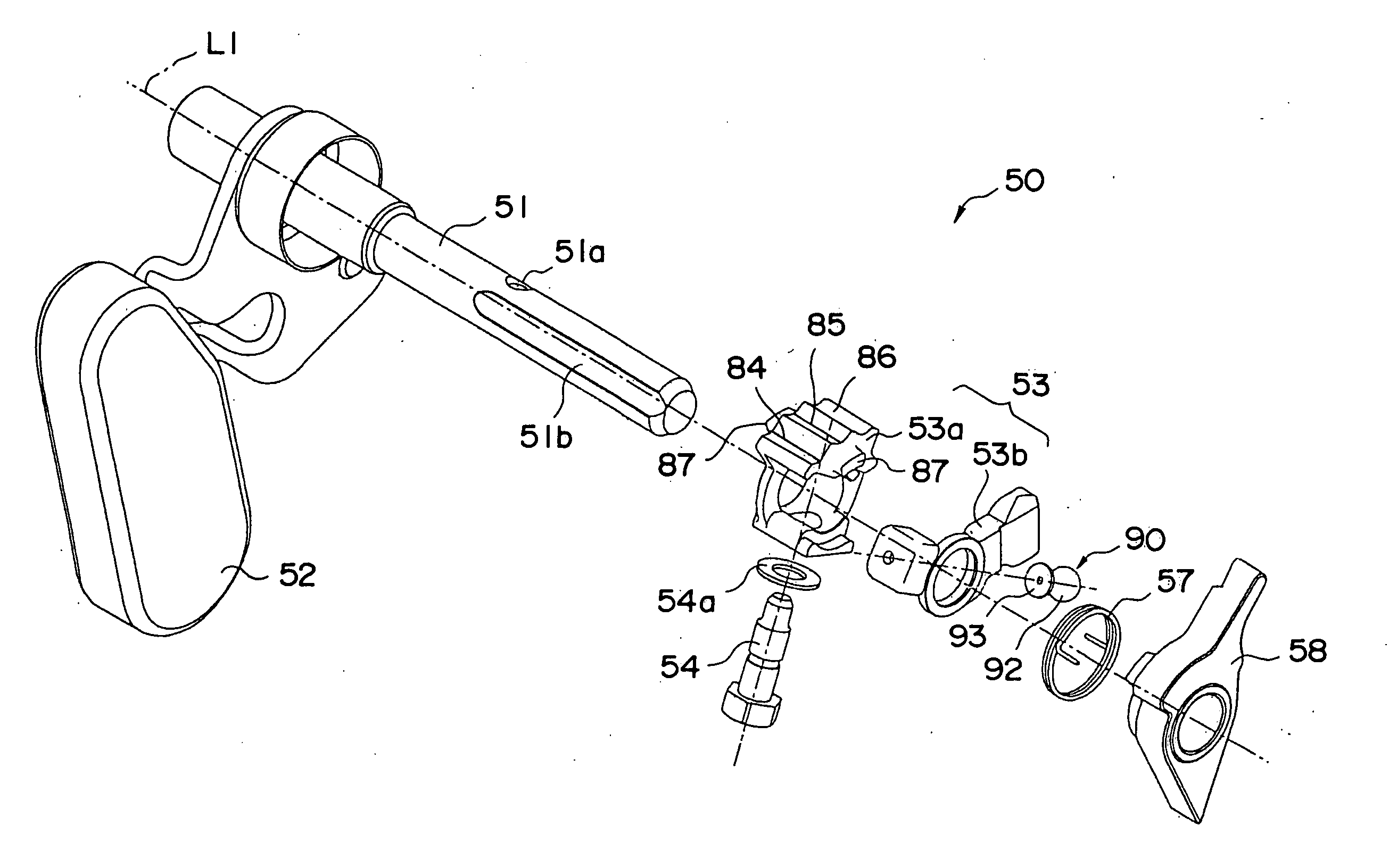
[0027] Now, a preferred embodiment of gear-shifting device for a manual transmission according to the present invention is described in reference to FIGS. 1˜7.

[0028] This manual transmission transmits the driving force of an engine with speed ratio change control, in which Low, 2nd˜5th and Reverse clutches are selectively engaged by the driver who operates the change-lever L provided at the driver seat. Therefore, at first, the system that transmits this operational force is described in the following.

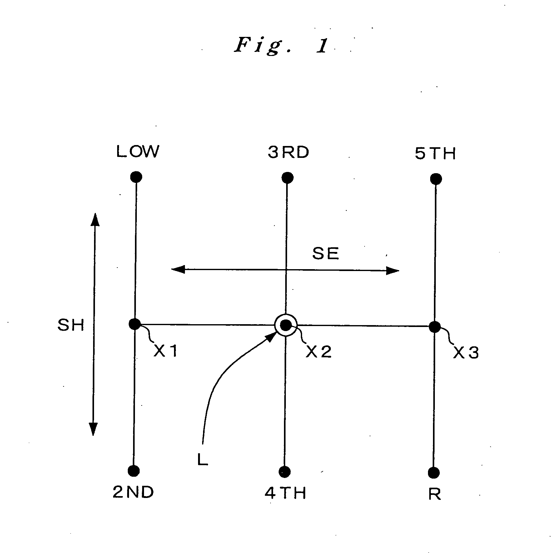
[0029] The change-lever L, which is used to select one of the 1st˜5th speed change ratios and reverse ratio (hereinafter referred to as “R speed”), is operated in the patterns shown in FIG. 1. If the change-lever L is operated in the direction indicated by SE in the drawing, then it can be positioned at one of the three selecting positions: 1st-2nd speed selecting position X1, 3rd-4th speed selecting position X2, and 5th-R speed selecting position X3. Then, while the change-lever L i...


PUM


Abstract

A gear-shifting device 50 for a manual transmission comprises a shift arm 53, which is rotatable in correspondence to the shift operation of a change-lever L, and shift pieces 41, 43 and 45, each of which shifts in correspondence to the rotation of the shift arm 53, with this shifting of the shift piece 41 achieving a gear shift. The gear-shifting device 50 further comprises a load-attenuating mechanism 90, which includes a spline groove 51b, a fitting room 91, a steel ball 92 and a coned spring 93. In the attenuating mechanism, the steel ball 92 is pushed to the spline groove 51b by the coned spring 93, allowing the shift arm 53 to rotate with respect to the shift selector shaft 51 to reduce the load acting on the change-lever L from synchro-sleeves 71, 73 and 75.

Description

FIELD OF THE INVENTION [0001] The present invention relates generally to a gear-shifting device for a manual transmission, which device actuates a shift fork to bring into engagement selectively a clutch that establishes a power transmission through a corresponding gear train in gear-shifting control. The present invention relates particularly to a gear-shifting device in which a force applied in operating the change-lever manually is transmitted selectively to a shift fork to bring a corresponding clutch into engagement in the manual transmission. BACKGROUND OF THE INVENTION [0002] Generally, in a manual transmission (manual gear-shift transmission), when the driver operates the change-lever for a shift, the force applied by the driver in the operation is transmitted through a gear-shifting device to a shift fork, so that the shift fork sets a corresponding clutch (for example, a synchromesh mechanism) into engagement, establishing a desired speed change ratio for the transmission....

Claims


Application Information

Patent Timeline
IPC IPC(8): F16D23/12F16D23/06F16H63/20F16H63/30
CPCF16H63/20F16H63/30F16H63/3408F16H63/38Y10T74/20183F16H2063/3083F16H2063/3089Y10T74/20177F16H2063/3076
Inventor MURAI, AKIFUMISAITOU, SUSUMU
Owner HONDA MOTOR CO LTD
Why Eureka
Try Eureka