Cooking device

a technology of cooking device and cooking time, which is applied in the field of cooking device, can solve the problems of increasing power consumption but not noise, requiring rather a long time for cooking, and achieve the effects of enhancing cooking performance, shortening cooking time, and no degradation of cooking performan

Inactive Publication Date: 2005-01-13
SHARP KK
View PDF17 Cites 17 Cited by
  • Summary
  • Abstract
  • Description
  • Claims
  • Application Information

AI Technical Summary

Benefits of technology

[0065] In this construction, when the fan is rotating in one direction, the air volume and/or the wind speed of the air blown out via the blowoff port formed in the surface that faces the surface on which the cooking target is placed is much higher than the air volume and/or the wind speed of the air blown out via the other blowoff port; when the fan is rotating in the opposite direction, the air volume and/or the wind speed of the air blown out via the blowoff port formed in the surface that faces the surface on which the cooking target is placed is slightly lower than the air volume and/or the wind speed of the air blown out via the other blowoff port. Thus, with almost no degradation in

Problems solved by technology

This cooking method, however, has the disadvantage of requiring rather a long time for cooking.
This, however, results in not only greatly increased power consumption but also greatly increased noise, which constitutes a critical drawback.
However, the hot-air-impact method is unsuitable for the cooking of sponge cake or the like, i.

Method used


Image

  • Cooking device
  • Cooking device
  • Cooking device

Examples


first embodiment

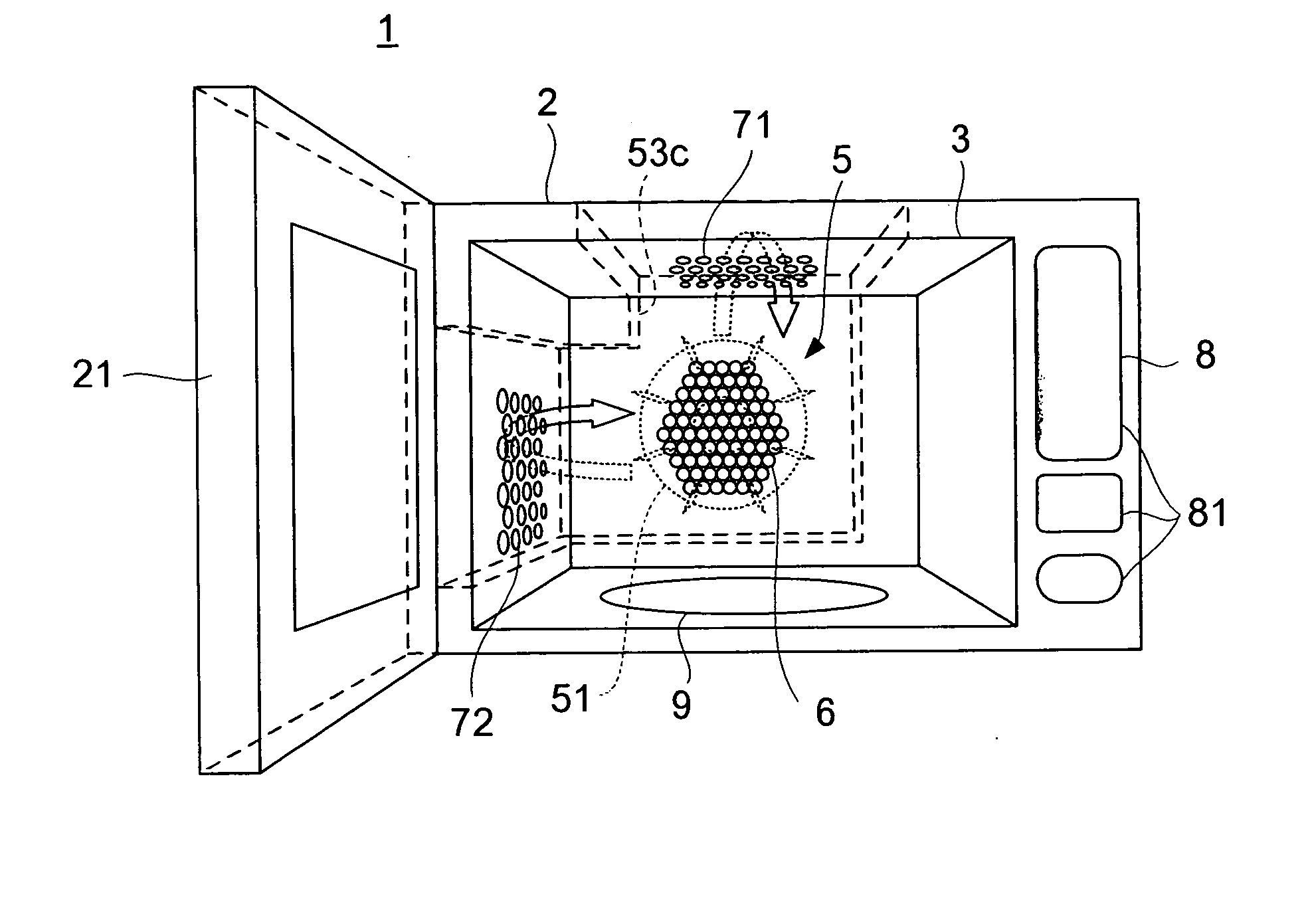
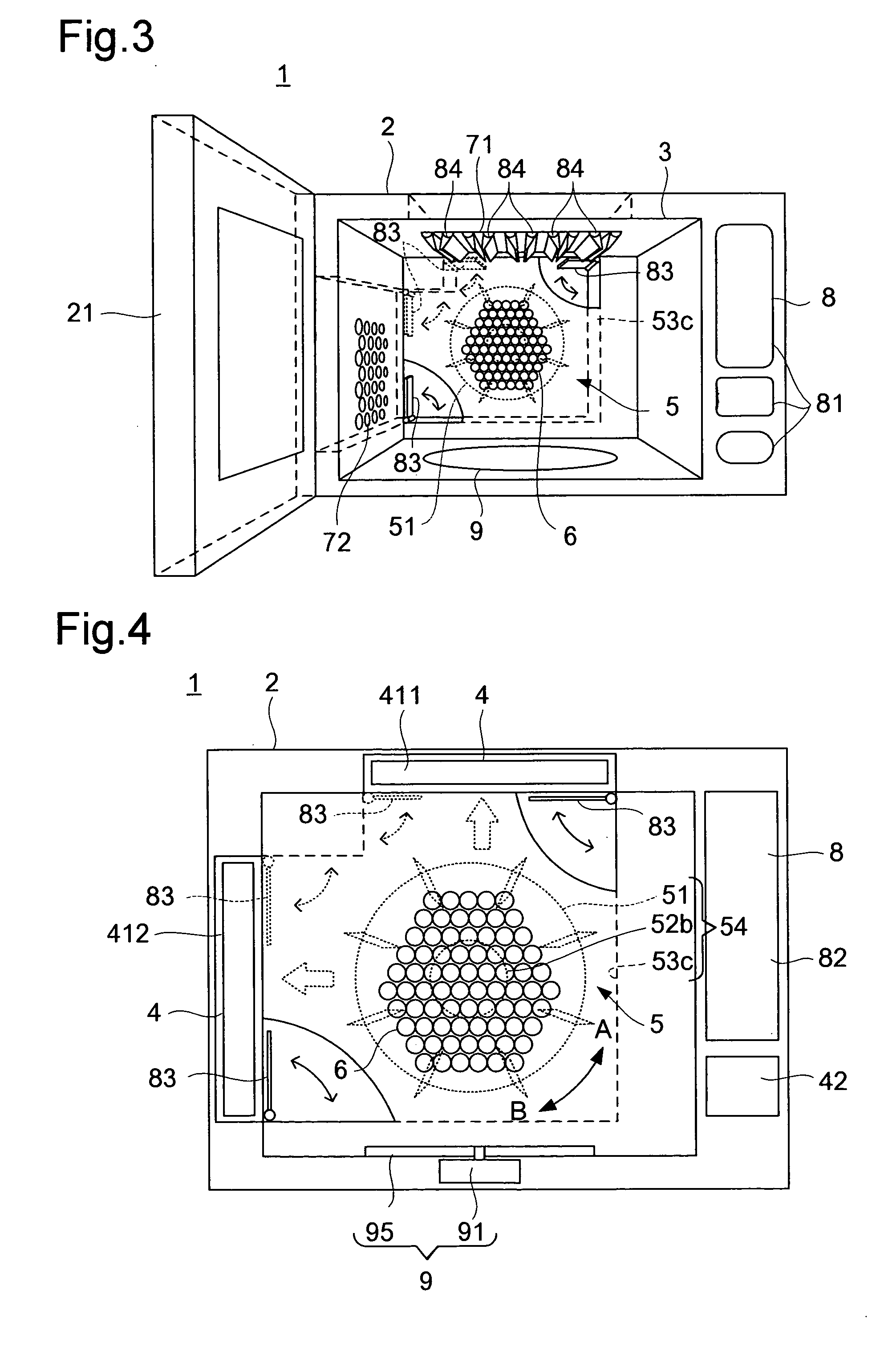
[0099] Inside the two-way branch fan casing 53c, there is provided a damper device 83. The damper device 83 permits adjustment of the wind volumes sent from the blowing machine 54 in the direction of the ceiling-surface blowoff port 71 and in the direction of the side-surface blowoff port 72. Moreover, at the ceiling-surface blowoff port 71, there is provided a throttling device 84. The throttling device 84 permits adjustment of the wind speed blown out via the ceiling-surface blowoff port 71. In other respects, the cooking device 1 of this embodiment is constructed in the same manner as the cooking device 1 of the first embodiment, and therefore such components as are common to the two embodiments are identified with the same reference numerals, and their explanations will not be repeated.

[0100] Constructed as described above, the cooking device 1 of this embodiments offers the same effects as the cooking device 1 of the first embodiment. In addition, in this embodiment, by control...

fifth embodiment

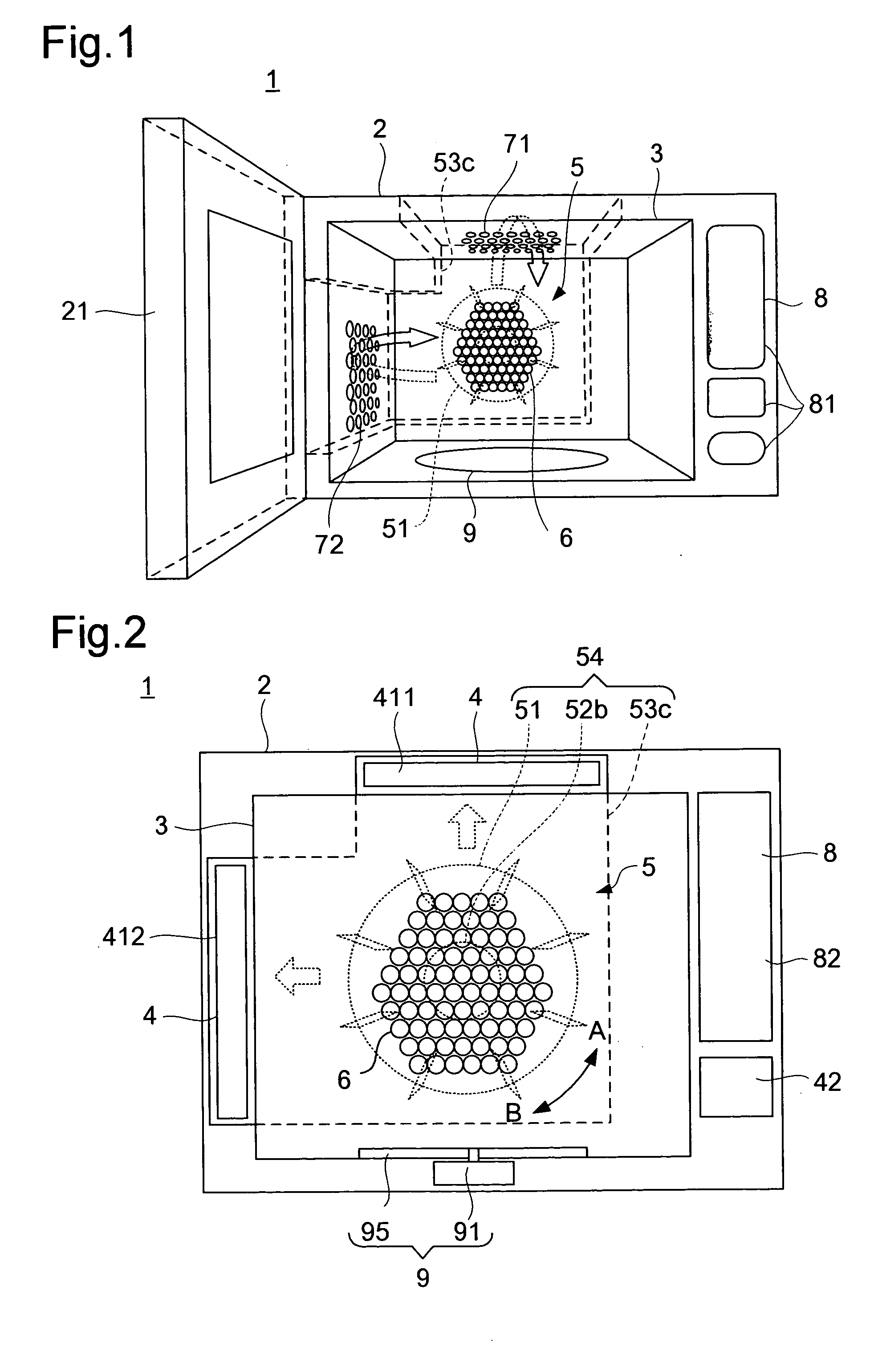
[0116] In the ceiling surface of the heating chamber 3, there is provided a blowoff port 7 provided with a throttling device 84. The air sucked in via the suction port 6 by the blowing machine 54 is heated by the heater 41, and is blown out via the blowoff port 7 into the heating chamber 3. Meanwhile, the wind speed of the air thus blown out is adjusted by the throttling device 84. In other respects, the cooking device 1 of this embodiment is constructed in the same manner as the cooking device 1 of the fifth embodiment, and therefore such components as are common to the two embodiments are identified with the same reference numerals, and their explanations will not be repeated.

[0117] In the cooking device 1 constructed as described above, when the user puts a cooking target on a meshed rack (not illustrated) placed on the turntable 95 and enters instructions via the operation panel 81 (see FIG. 1), according to the instructions entered via the operation panel 81, the controller 82 ...

seventh embodiment

[0146] Constructed as described above, the cooking device 1 of this embodiments offers, in addition to the effects offered by the cooking device 1 of the seventh embodiment, the following effects.

[0147] When the centrifugal fan 51 is rotated by the reversible motor 52B at a high rate in the direction indicated by arrow A shown in FIG. 15, the wind volume that passes through the air-blow passage 56a becomes far higher than the wind volume that passes through the air-blow passage 56b. Moreover, since the air-blow passage 56a becomes increasingly large along the air-blow direction, it functions as a so-called diffuser by converting the kinetic energy of the flowing wind into a static pressure. This greatly augments the wind guided upward from the heater 41 as compared with the same wind in the cooking device 1 of the seventh embodiment. This enhances the performance of the centrifugal fan 51, and thus, even if the rotation rate of the centrifugal fan 51 is made lower than in the cookin...


PUM


Abstract

A cooking device, wherein, when a roast chicken is selected from a menu displayed on an operating part (81), a centrifugal fan (51) is controlled so as to be rotated in forward direction at a high speed to blow out hot air with a speed of 65 km/h or faster from upper blowout ports (71) and hot air with a speed of 30 km/h or slower from side blowout ports (72) whereby a roast chicken in a heating chamber (3) can be cooked at the high speed and, when a sponge cake is selected from the menu, the centrifugal fan (51) is controlled so as to be rotated in reverse direction at a low speed to blow out hot air with a speed of 30 km/h or slower from the upper blowout ports (71) and hot air with a speed of 40 km/h or slower from the side blowout ports (72) whereby a sponge cake in the heating chamber (3) can be cooked light and fluffy.

Description

TECHNICAL FIELD [0001] The present invention relates to a cooking device, such as a convection oven or a hot-air-impact oven, for cooking a cooking target with heat. BACKGROUND ART [0002] A cooking device 100 known as a convection oven for cooking a cooking target with heat is typically constructed as shown in FIG. 17. FIG. 17 is a diagram showing an outline of the construction of such a conventional cooking device 100. In FIG. 17, the cooking device 100 is composed of: a box-shaped member 2 that is thermally insulated; a heating chamber 3 that is formed inside the box-shaped member 2 to permit a cooking target to be placed therein; heating means 4 that heats the cooking target placed in the heating chamber 3; and blowing means 5. The blowing means 5 is provided with a blowing machine 54, which is composed of: a centrifugal fan 51; a drive motor 52 that drives the centrifugal fan 51; and a fan casing 53 that communicates with the heating chamber 3 through a suction port 6 and a blow...

Claims


Application Information

Patent Timeline
IPC IPC(8): F24C15/32
CPCF24C15/325
Inventor OHTSUKA, MASAKISHIRAICHI, YUKISHIGE
Owner SHARP KK
Why Eureka
Try Eureka