Feedforward controller for synchronous reluctance machines

a technology of synchronous resistance and feedback controller, applied in the field of electromechanical arts and energy storage systems, can solve the problems of less appropriate time control theory used to develop feedback controllers, challenges to traditional electromechanical energy exchange solutions,

Active Publication Date: 2005-01-13
BEAVER AEROSPACE & DEFENSE
View PDF13 Cites 27 Cited by
  • Summary
  • Abstract
  • Description
  • Claims
  • Application Information

AI Technical Summary

Problems solved by technology

Advanced mechanical energy storage devices like high speed flywheels pose new challenges to traditional electromechanical energy exchange solutions.
This creates difficulties with feedback control techniques typically used to control these systems since the assumptions of continuous-time control theory typically used to develop feedback controllers become less appropriate.

Method used


Image

  • Feedforward controller for synchronous reluctance machines
  • Feedforward controller for synchronous reluctance machines
  • Feedforward controller for synchronous reluctance machines

Examples


Embodiment Construction

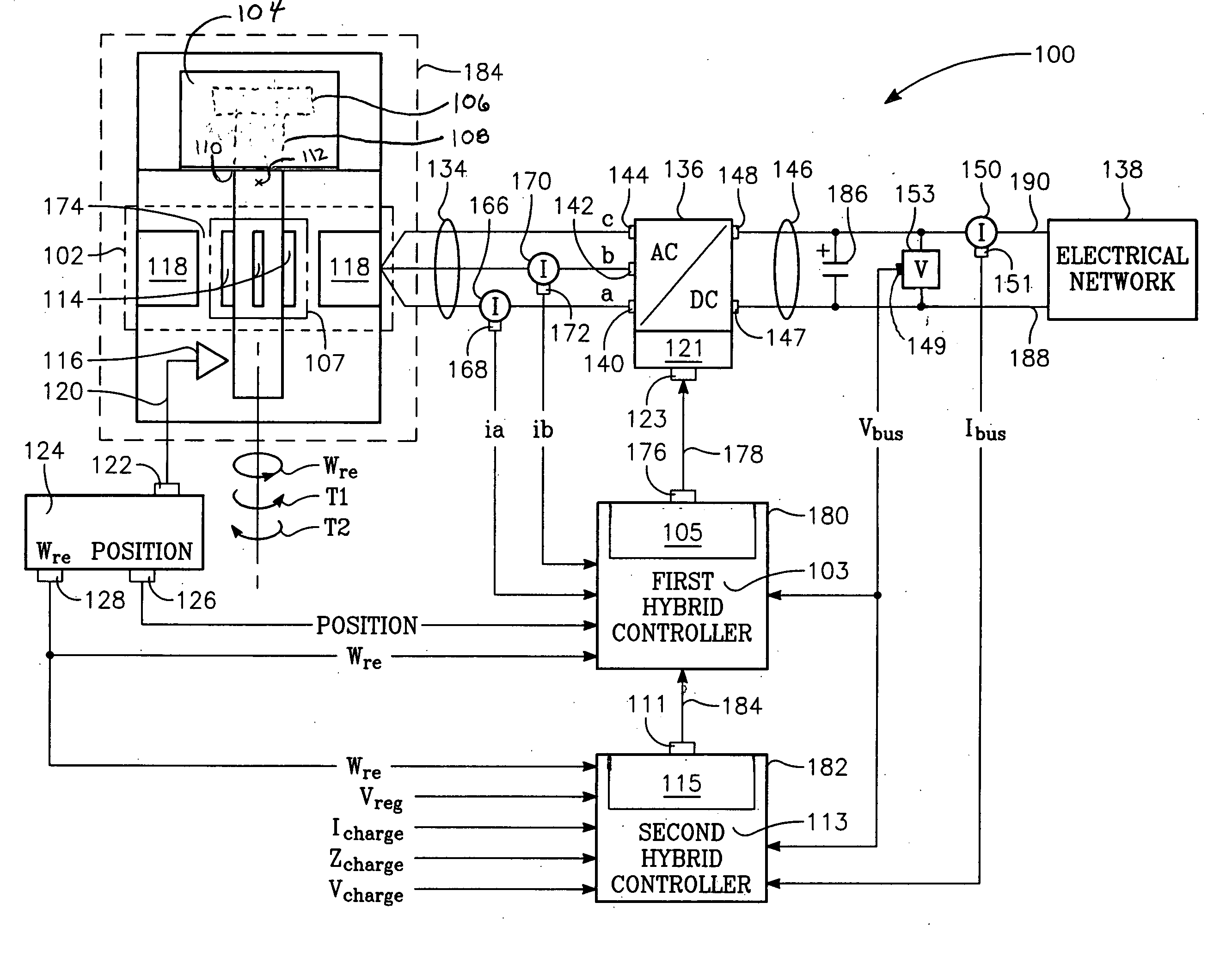
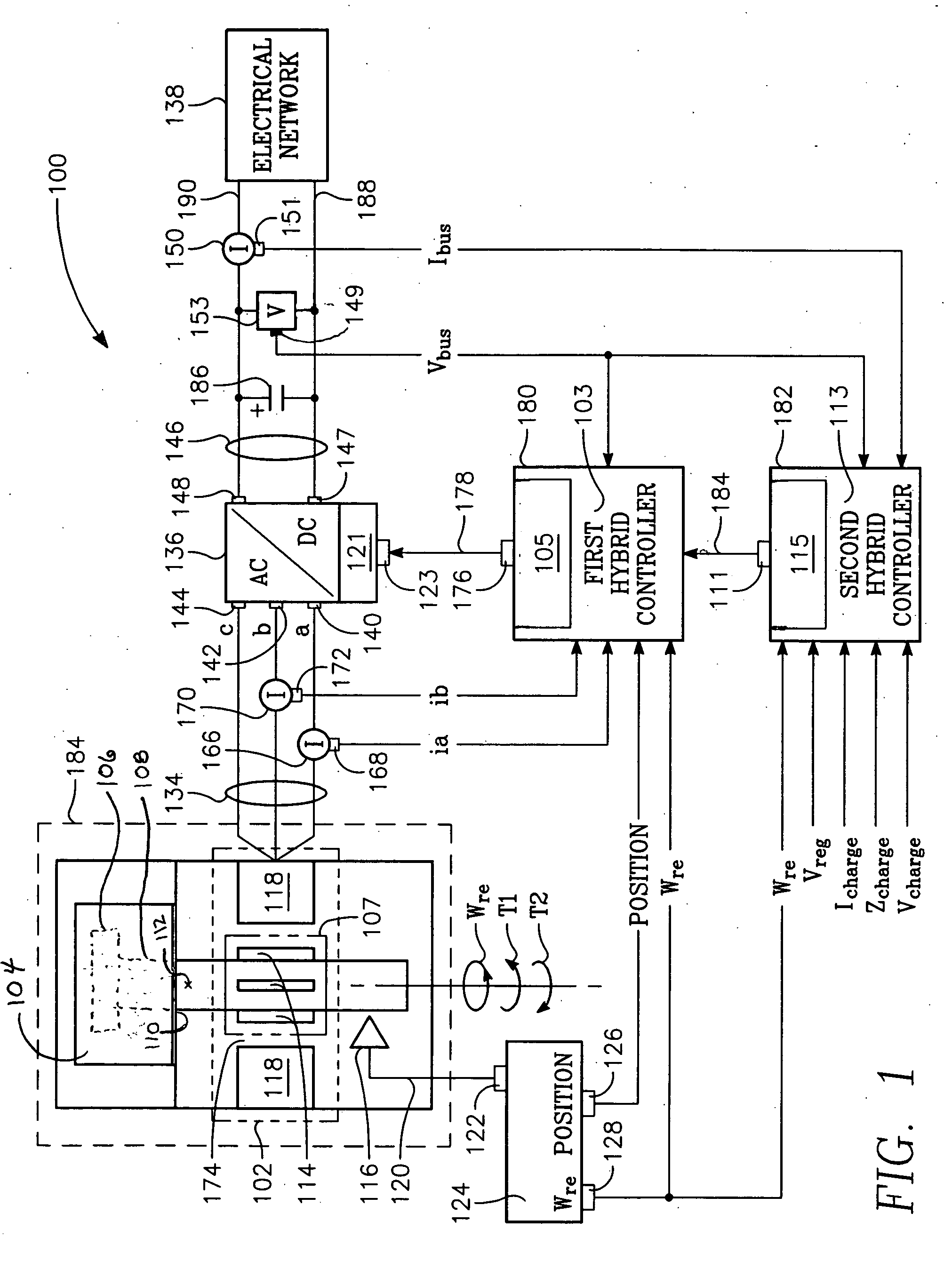
FIG. 1 shows the feedforward controller for a synchronous reluctance machine 100 of the present invention. The feedforward controller for a synchronous reluctance machine includes synchronous reluctance machine module 184, bi-directional AC-to-DC electric power converter 136, first hybrid controller 180, and second hybrid controller 182.

The machine module 184 includes a synchronous reluctance motor-generator 102. The motor-generator includes a rotor 107 having a plurality of rotor lobes 114 and an electrical stator 118 spaced apart from the rotor by an air gap 174. The rotor 107 may be an all-metal rotor formed entirely from electrically conductive materials. The rotor is integral with a first shaft portion 112. The first shaft portion has a shaft coupling 110 that is connected to a mechanical energy exchange device 104 and rotates at an angular velocity wre. A shaft speed transducer 116 is proximate to the first shaft portion. A rotor position signal conductor 120 interconnects th...


PUM


Abstract

The present invention provides an electromechanical energy exchange system with a variable speed synchronous reluctance motor-generator having an all-metal rotor. A bi-directional AC-to-DC electric power converter interconnects the motor-generator with a DC bus. First and second hybrid controllers provide current regulation for the motor-generator and voltage regulation for the DC bus. Use of both feedback and feedforward control elements provides a controller particularly suited for operating high speed devices.

Description

BACKGROUND OF THE INVENTION 1. Field of the Invention The present invention relates to the electromechanical arts and energy storage systems. In particular, the present invention pertains to mechanical energy exchange systems coupled with electrical energy exchange systems. 2. Description of Related Art Electro-mechanical energy exchange systems have provided mechanical and electrical power solutions for over one hundred years. These solutions have typically involved a prime mover driving an AC generator at a fixed speed multiple of the synchronous frequency. These power solutions have not required electronic processing of the generator output since the generator is a constant speed machine able to generate a sinusoidal electric output at the desired fixed frequency. Advanced mechanical energy storage devices like high speed flywheels pose new challenges to traditional electromechanical energy exchange solutions. No longer able to rely on fixed speed operation and the attendant...

Claims


Application Information

Patent Timeline
Patent Type & Authority Applications(United States)
IPC IPC(8): H02P9/30H02P21/00H02P21/06H02P25/08
CPCH02P9/30H02P25/08H02P21/06
Inventor HOFMANN, HEATH F.KHALIZADEH, CLAUDE
Owner BEAVER AEROSPACE & DEFENSE
Why Eureka
Try Eureka