

Method for manufacturing image display device, image display device, and TV apparatus
a technology of image display device and display device, which is applied in the direction of instruments, discharge tubes, tubes with screens, etc., can solve the problems of increasing the resultant cost of image display device, the difficulty of mass-producing spacers having such mechanical precision stably, etc., and achieves high mechanical precision, suppress discharge, and stabilize mechanical strength
- Summary
- Abstract
- Description
- Claims
- Application Information
AI Technical Summary
Benefits of technology
Problems solved by technology
Method used
Image

Examples
first embodiment
[0068] [First Embodiment]
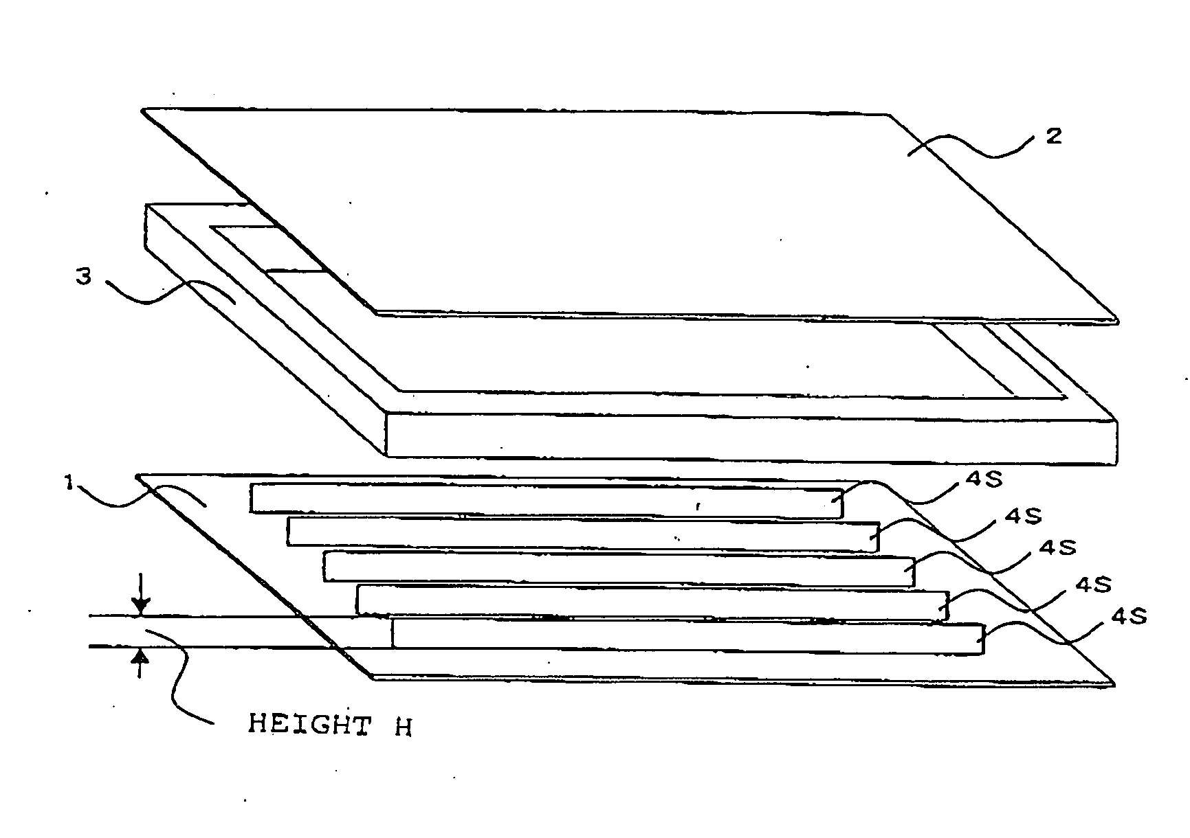
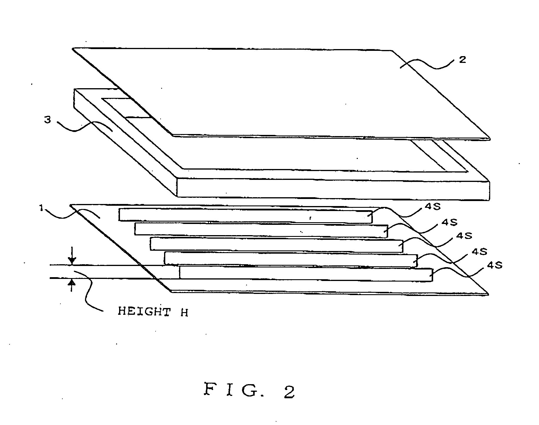
[0069] In this embodiment, plate-shaped spacers are used as support members. FIG. 2 is a view for explaining an arrangement of the plate-shaped spacers. Reference numeral 1 designates a rear plate; numeral 2 a front plate arranged opposite the rear plate 1; and numeral 3 an outer frame for forming a vacuum container. FIG. 2 shows the behavior, in which five plate-shaped spacers 4S are arranged, for example, between the rear plate 1 and the face plate 2.
[0070] Here, the plate-shaped spacers 4S can be prepared by a heating drawing. According to this heating drawing, it is possible (as referred to JP-A-2000-311608, for example) to easily prepare the plate-shaped spacers 4S which can suppress scattering of secondary electrons.
[0071] This embodiment is provided with measurement means for measuring the heights H (as referred to FIG. 2) of the individual plate-shaped spacers. FIG. 4 schematically shows the measurement points in the height measurements of the plat...
second embodiment
[0083] [Second Embodiment]
[0084] This embodiment is identical to the first embodiment excepting that the method of measuring the heights of the spacers is different, and the description of its similar construction will be omitted.
[0085] In this embodiment, the measured values of the heights of the individual plate-shaped spacers were measured at multiple points in the plate-shaped spacers, and their average value was used. Specifically, the individual plate-shaped spacers were arranged on the basis of the average value.
[0086]FIG. 4 shows the measurement points of the plate-shaped spacers. In this embodiment, the heights of the plate shaped spacers were measured at the individual measurement points (4Sa, 4Sb, 4Sc, 4Sd and 4Se) which had been set at equal distances in the longitudinal direction of the plate-shaped spacers.
[0087]FIG. 7 is a graph showing the individual measured height values at the five measurement points set at the individual plate-shaped spacers and their average ...
third embodiment
[0089] [Third Embodiment]
[0090] The fundamental construction of the image display device is identical to that of the first embodiment, and the description of a similar construction will be omitted.
[0091] Moreover, it is identical to the second embodiment that the heights of the individual plate-shaped spacers are measured at multiple points in the individual plate-shaped spacers so that their average value is determined. Therefore, the description of the identical point will be omitted. In this embodiment, the arrangement of the plate-shaped spacers is controlled by considering the in-plane distribution of the image display device due to the height irregularity with respect to the longitudinal direction of the plate-shaped spacers.
[0092]FIG. 9 shows a height distribution of the case, in which the plate-shaped spacers are arranged like the second embodiment in the sequential order from the larger average value. Moreover, the in-plane height distribution in this state is illustrated...
PUM
 Abstract
Description
Claims
Application Information